
Cylinder cap air valve spring cover, locking plate press-loading head

A valve spring and valve lock plate technology, which is applied in metal processing, metal processing equipment, manufacturing tools, etc., can solve the problems of large influence of the assembly quality workpiece itself, low efficiency, unstable assembly quality, etc., to ensure the assembly quality. Quality, easy installation and adjustment, stable and reliable equipment structure

Inactive Publication Date: 2008-10-08
DALIAN ZHIYUN AUTOMATION
View PDF0 Cites 14 Cited by
  • Summary
  • Abstract
  • Description
  • Claims
  • Application Information

AI Technical Summary

Problems solved by technology

The efficiency of this method of assembly is low, and the assembly quality is greatly affected by the accuracy of the workpiece itself
Therefore, in mass production, the contradictions of low efficiency and unstable assembly quality are more prominent, and a new press-fitting head is needed to improve production quality

Method used


Image

  • Cylinder cap air valve spring cover, locking plate press-loading head
  • Cylinder cap air valve spring cover, locking plate press-loading head
  • Cylinder cap air valve spring cover, locking plate press-loading head

Examples


Embodiment Construction

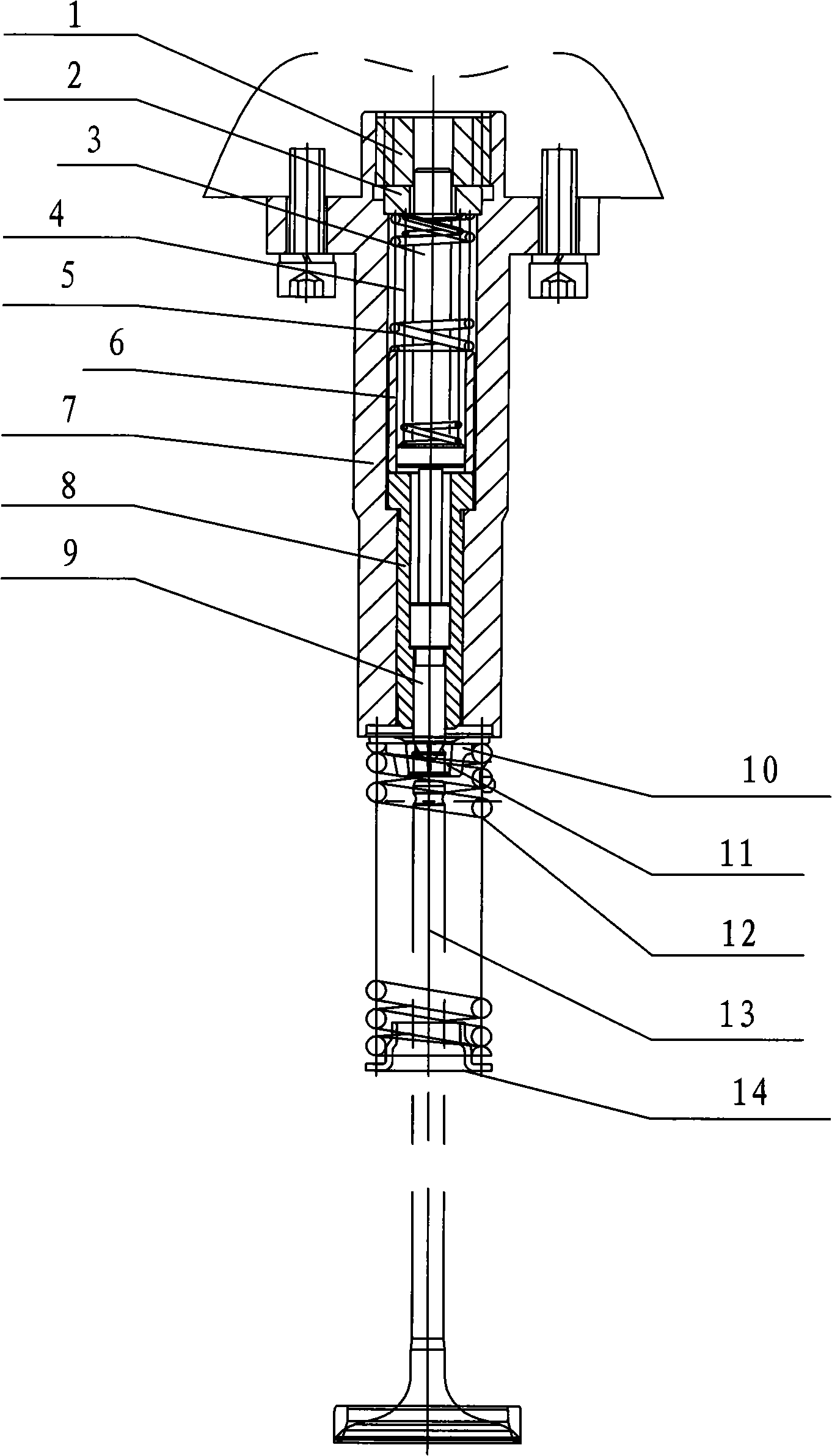
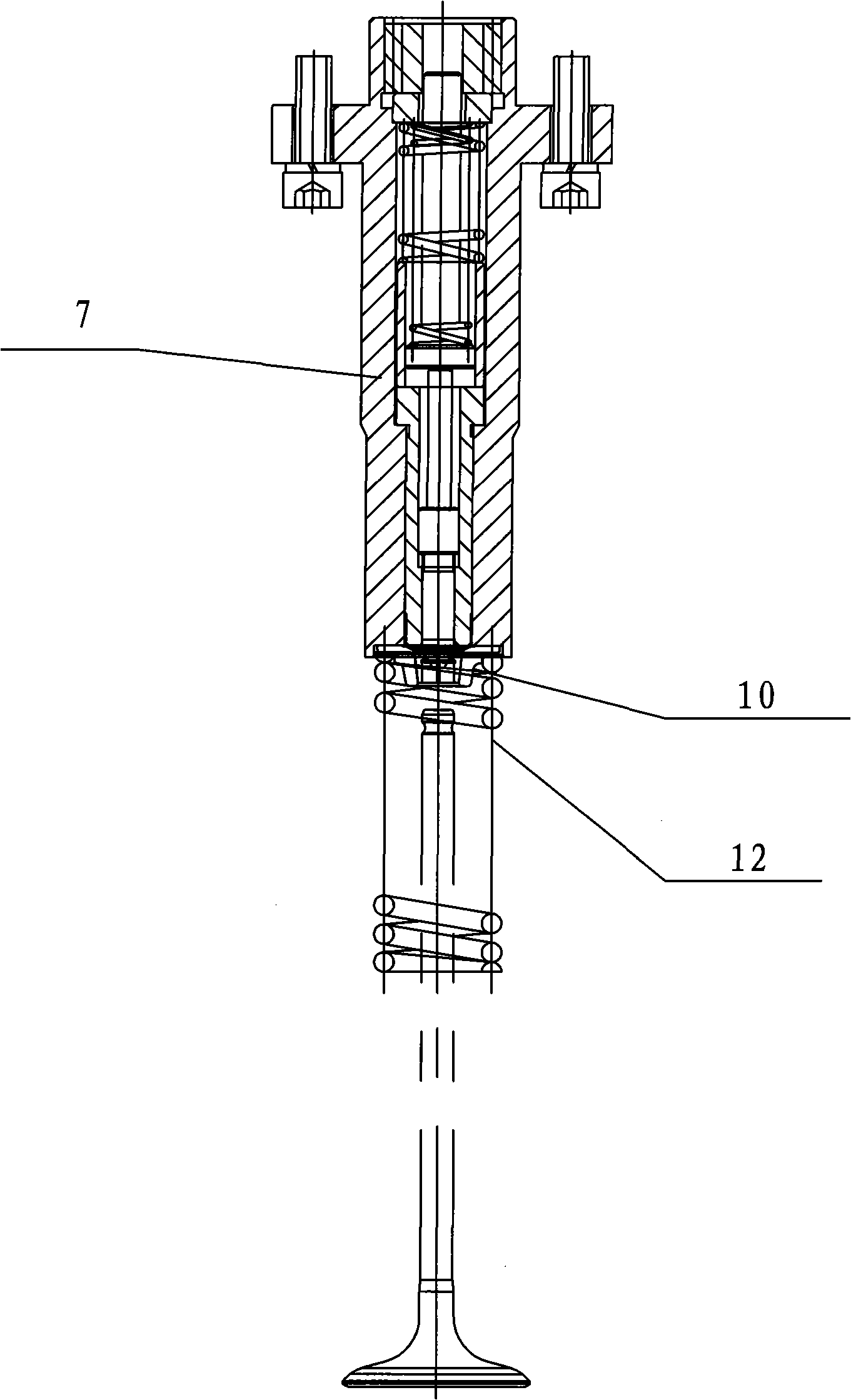
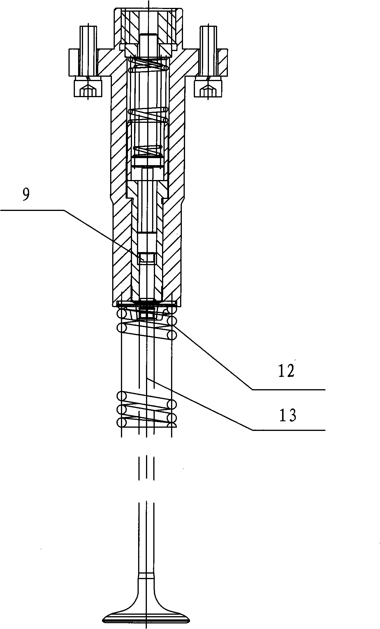
[0021] Such as Figure 1-Figure 7 As shown, a cylinder head valve spring cover, lock plate pressing head, including: compression screw plug 1, spring cover 2, ejector rod 3, inner ring spring 4, outer ring spring 5, sleeve 6, pressure head jacket 7. The core sheath 8 and the indenter core 9; it is characterized in that there is a through hole in the middle of the indenter jacket 7, in which the ejector rod 3 and the indenter core 9 are installed, and the two are freely connected; the ejector rod 3 An inner spring 4 and an outer spring 5 are installed on the top, and a spring gland 2 is arranged on the inner and outer springs, and the spring gland 2 is set on the push rod 3, and the compression screw plug 1 and the pressure head The jacket 7 is threadedly connected; a core sheath 8 is also provided between the pressure head core body 9 and the pressure head jacket 7; there are related valve spring covers 10, valve lock plates 11, and valves under the core sheath. Spring 12, va...


PUM


Abstract

The invention discloses a cylinder cover valve spring cover and a keeper pressing assembly device, which are characterized in that the invention comprises a pressing head external bushing which is provided with an ejector pin and a pressure head core body; the ejector pin is sheathed with an internal spring and an external spring and a spring pressure cover is sheathed on the ejector pin; a compression plug screw on the ejector pin is connected with the pressing head external bushing by screw thread; a core body sheath is arranged outside the pressure head core body, and the valve spring cover, a valve split collet, a valve spring, a valve ejector pin and related parts for a valve spring retainer are arranged below the core body sheath in sequence. The process of pressing and assembly comprises 6 actions; wherein, the pressing head external bushing is driven to be contacted with the valve spring by Action I; the pressure head core body is driven to be contacted with the ejector pin by Action II; the core body sheath is driven to be contacted with the valve split collet and the side of the pressure head core body is caused to slide into the end part of the valve ejector pin by Action III; the valve split collet is pressed into a space below the end part of the valve ejector pin by Action IV; the valve split collet is pressed into a space below a ring-shaped groove at the end part of the valve ejector pin by Action V; a pressure head is lifted, the valve spring is reset and the valve split collet is clamped into the ring-shaped groove of the valve ejector pin by Action VI.

Description

technical field [0001] The invention relates to a cylinder head valve spring cover and a locking plate pressing device, which is used for pressing the cylinder head valve spring cover and the locking plate in mass production and manufacturing of engines. Background technique [0002] At present, in the production and manufacture of engines, many manufacturers still use simple hollow press-fitting heads for the press-fitting of cylinder head valve spring covers and locking plates. The efficiency of this method of assembly is low, and the assembly quality is greatly affected by the accuracy of the workpiece itself. Therefore, in mass production, the contradictions of low efficiency and unstable assembly quality are more prominent, and a new press-fitting head is needed to improve production quality. Contents of the invention [0003] In order to overcome the shortcomings of the existing press-fitting methods, the invention provides a cylinder head valve spring cover and a l...

Claims


Application Information

Patent Timeline
Patent Type & Authority Applications(China)
IPC IPC(8): B23P19/02
Inventor 赵天明何忠连雄周爱龙张绍辉
Owner DALIAN ZHIYUN AUTOMATION
Learn More