
Ultrasonic flexural vibration device

A bending vibration and ultrasonic technology, applied in the direction of fluid, solid separation, filter screen, etc. using vibration, can solve the problems of unable to increase the power of the transducer, limit the ultrasonic cleaning function, hinder the application of ultrasonic technology, etc., so as to reduce the loosening phenomenon. , The effect of widening the ultrasonic working frequency band and increasing the power application value

Active Publication Date: 2008-10-08
GUANGZHOU NEWPOWER ULTRASONIC ELECTRONICS EQUIP
View PDF5 Cites 5 Cited by
  • Summary
  • Abstract
  • Description
  • Claims
  • Application Information

AI Technical Summary

Problems solved by technology

The current ultrasonic cleaning equipment is generally on the basis of adhesive assisted paste, and the transducer is directly screwed to the bottom of the cleaning tank or the outer wall of the side by using screws. Although this structure can play the role of ultrasonic cleaning, its limitation is that The power of the transducer cannot be greatly increased, which limits the optimization of the ultrasonic cleaning function, hinders the development of production scale, and also hinders the application of ultrasonic technology in sonochemistry and ultrasonic extraction to a certain extent.

Method used


Image

  • Ultrasonic flexural vibration device

Examples


Embodiment Construction

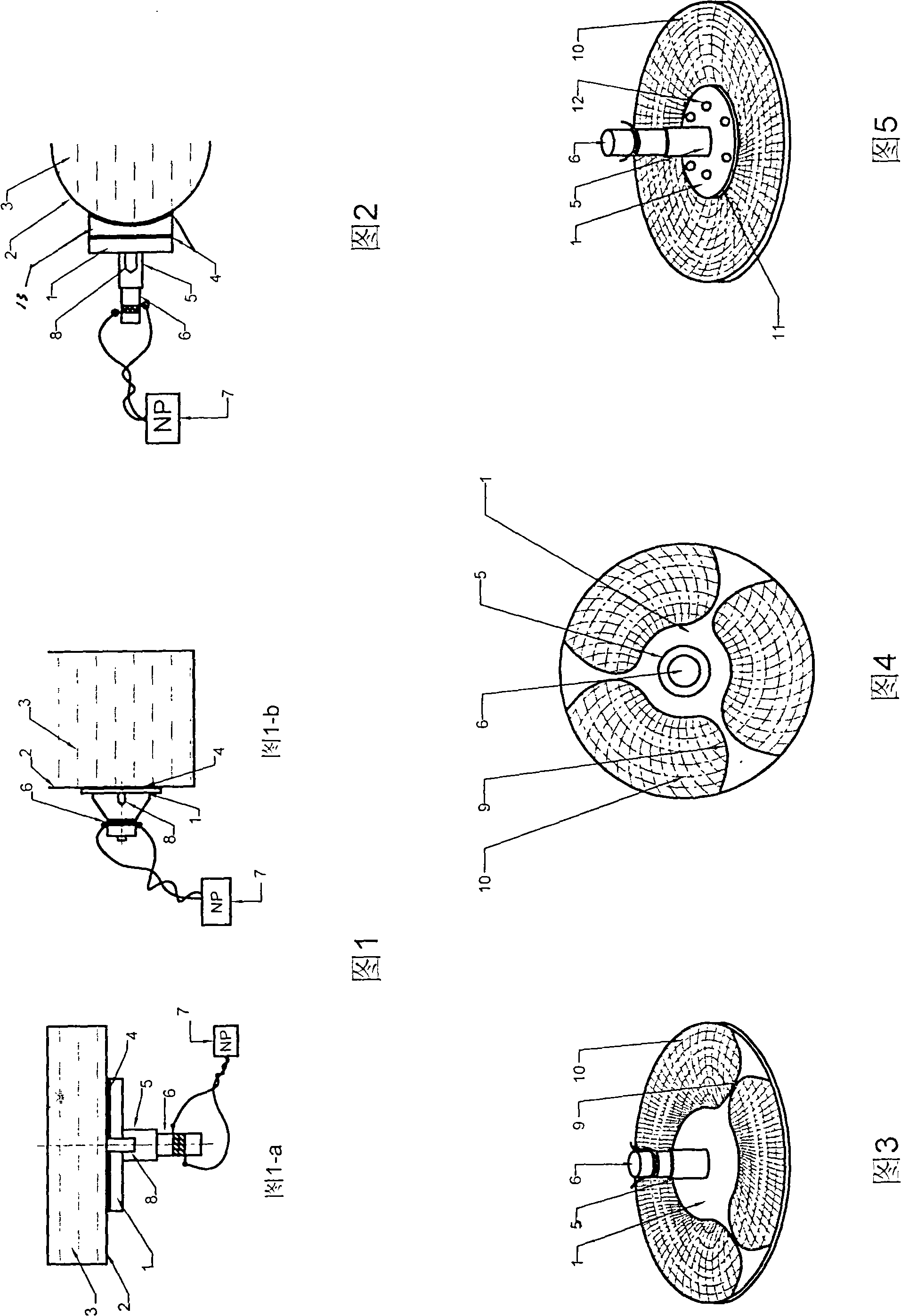
[0023] As shown in Figures 1 to 5, in Figures 1-a and 1-b, the power-expanding front metal vibration plate 1 and the horn 5 are arranged between the bottom plate 2 of the functional slot 3 and the transducer 6, and the variable The front end surface of the horn 5 is connected with the power-expanding front metal vibration plate 1 , and the rear end surface is connected with the front block of the transducer 6 . The screw 8 is vertically welded on the bottom plate 2, and screw holes corresponding to the size of the screw 8 are respectively set in the center of the metal vibration plate and the center of the horn before the power expansion. on the bottom plate 2. Adhesive 4 is applied between the pre-power expansion metal vibration plate and the bottom plate of the functional slot. When the central screw hole of the pre-power expansion metal vibration plate is screwed into the outer wall of the bottom plate of the function slot along the longitudinal direction of the screw, the ...


PUM


Abstract

The invention relates to a large power ultrasonic bending vibration device which comprises a functional slot bottom plate, a transducer, an amplitude transformer, a front-arranged power amplifying metal vibration plate, a welding bolt and an ultrasonic wave generator. The invention is characterized in that the front-arranged power amplifying metal vibration plate and the amplitude transformer are arranged between the functional slot bottom plate of a touch piece which receives ultrasonic irradiation and the transducer; the front end surface of the amplitude transformer is connected with the front-arranged power amplifying metal vibration plate; the back end surface is connected with a front-arranged block of the transducer; the front-arranged power amplifying metal vibration plate and the amplitude transformer are screwed by the welding bolt tightly and sequentially and stuck on the functional slot bottom plate of the touch piece which receives ultrasonic irradiation. The large power ultrasonic bending vibration device of the invention has a novel structure, can improve the power of the transducer to a large extent, has a large ultrasonic irradiation action area, increases the ultrasonic cavitating function, reduces the ultrasonic cavitating corrosion degree of a stainless steel plate, effectively reduces the loosening phenomena of an ultrasonic vibrator, is beneficial to the ultrasonic vibrator to work under the condition of long continuous large power, broadens the working frequency bands, enhances the adaptation and is beneficial to manufacturing in batch and reducing cost.

Description

technical field [0001] The invention relates to an ultrasonic high-power bending vibration device, which is an innovation to the traditional ultrasonic vibration device, and belongs to the technical field of ultrasonic and electromechanical products. Background technique [0002] With the development of science and technology, the application of ultrasonic technology is becoming more and more common, such as ultrasonic cleaning, refinement, uniform mixing, dispersion, polymerization promotion, exhaust gas of liquid and slurry system materials, ultrasonic chemistry, ultrasonic extraction, ultrasonic crushing, Ultrasonic demulsification, phacoemulsification, ultrasonic wine aging, etc. Ultrasonic cleaning technology has attracted more and more attention due to its high cleaning efficiency and low energy loss. The current ultrasonic cleaning equipment generally uses screws to directly screw the transducer on the outer wall of the bottom or side of the cleaning tank on the basi...

Claims


Application Information

Patent Timeline
IPC IPC(8): B06B1/00B06B3/02B06B1/02B07B1/28B07B1/40
Inventor 严锦璇杨治中严卓理严卓晟
Owner GUANGZHOU NEWPOWER ULTRASONIC ELECTRONICS EQUIP
Learn More