Focal position determining method, focal position determining apparatus, feeble light detecting apparatus and feeble light detecting method

A focus position and determination technology, applied in the field of focus position determination devices, can solve problems such as weak light intensity and difficulty

Inactive Publication Date: 2008-10-01
OLYMPUS CORP
View PDF5 Cites 22 Cited by
  • Summary
  • Abstract
  • Description
  • Claims
  • Application Information

AI Technical Summary

Problems solved by technology

However, since the intensity of self-luminescence from biological samples is generally very weak, it is often impossible to directly confirm the luminescence from biological samples with the naked eye.
For such a sample that emits weak light, even if the optical element (such as the lens of the detection system, etc.) is adjusted, it is very difficult to focus the lens on the part of the sample with the naked eye.

Method used


Image

  • Focal position determining method, focal position determining apparatus, feeble light detecting apparatus and feeble light detecting method
  • Focal position determining method, focal position determining apparatus, feeble light detecting apparatus and feeble light detecting method
  • Focal position determining method, focal position determining apparatus, feeble light detecting apparatus and feeble light detecting method

Examples


no. 1 Embodiment approach

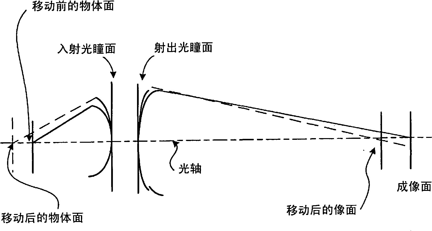
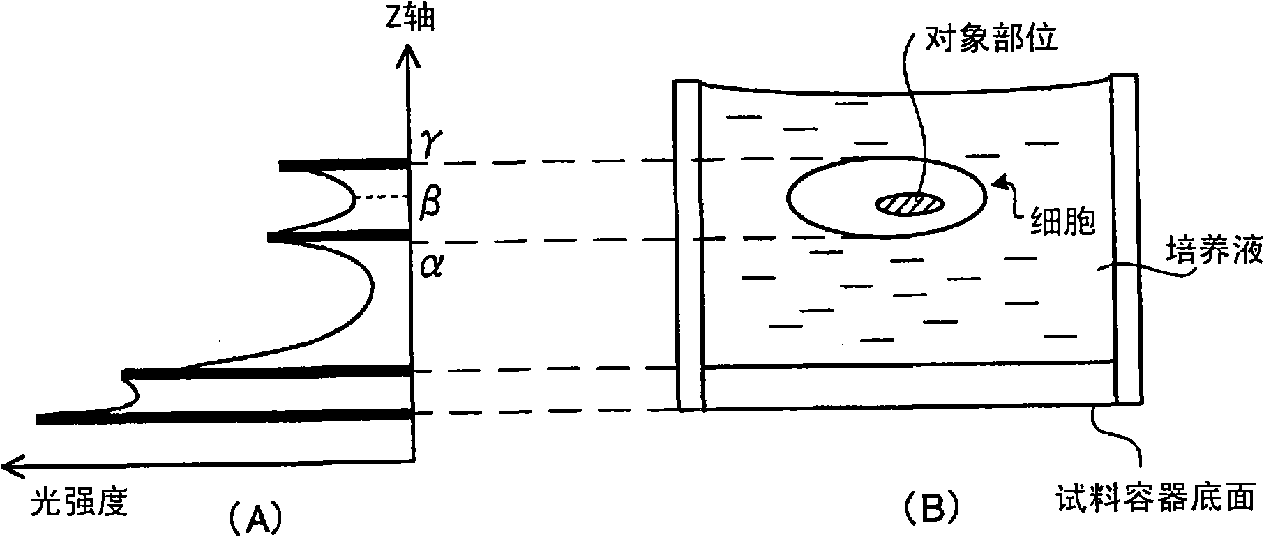
[0174] First, the basic principles of the present invention will be described in detail with reference to the drawings. The present invention determines the focal position of the objective lens as a reference, and uses the determined focal position as a reference to measure the focal position (approximate focal position) of the near point side of the objective lens and / or the focal position (approximate focal position) of the far point side of the objective lens, Based on the measured focus position, the focus position of the objective lens aimed at the observation target site in the sample is determined, and the focus position of the objective lens is aligned (moved) to the determined focus position.

[0175] Specifically, in the present invention, (1) irradiating light to the sample, (2) moving the position of the sample and / or the position of the objective lens along the optical axis direction and / or changing the focal length of the objective lens (here In the case of a var...

no. 2 Embodiment approach

[0265] Next, refer to Figure 20 to Figure 22 The configuration of the focus position determination device 1 according to the second embodiment of the present invention will be described in detail. In addition, the description overlapping with the description of the above-mentioned first embodiment may be omitted.

[0266] FIG. 20 is a diagram showing a specific example of the configuration of the focus position determination device 1 according to the second embodiment. The focus position determining device 1 shown in FIG. 20 is based on an inverted microscope, and is used for simultaneous luminescence observation and fluorescence observation of living cells that emit weak light. The focus position determination device 1 determines the focus of the objective lens 30 aligned with the observation target site 10a in the sample 10 when the sample 10 such as biological cells or tissues is set when the fluorescence observation and the luminescence observation are performed simultan...

no. 3 Embodiment approach

[0301] Next, the outline, configuration, and processing of a focus position determination device 1 ′ according to a third embodiment of the present invention will be described in detail with reference to the drawings. In addition, content overlapping with the description of the above-mentioned first embodiment or second embodiment may be omitted.

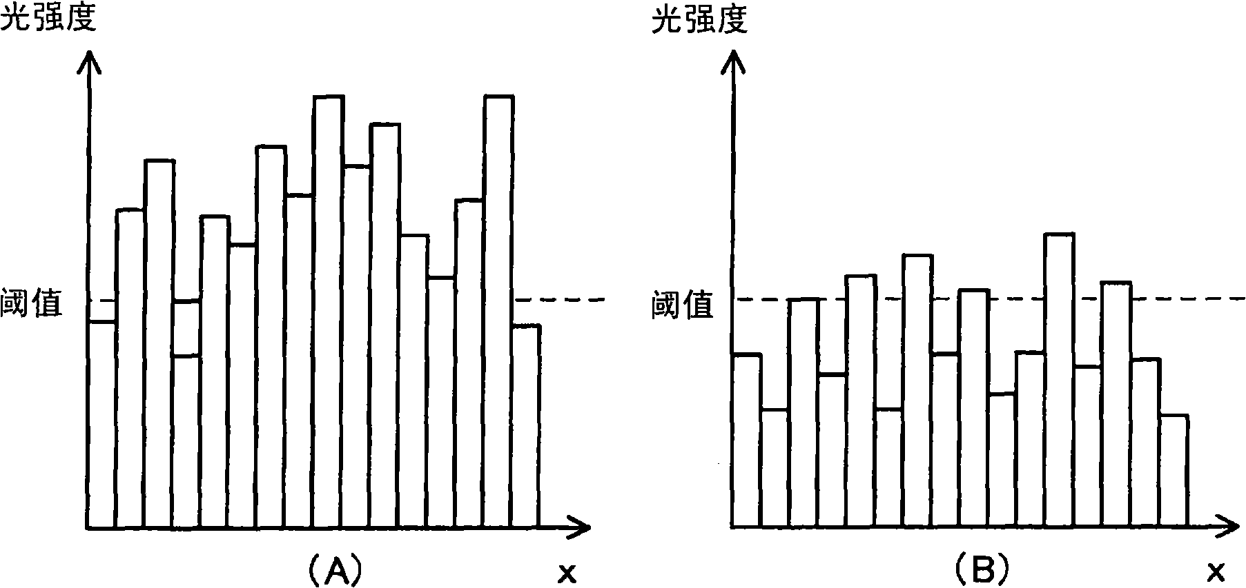
[0302] First, the outline of the present invention will be described in detail. The present invention images a sample (specifically, a biological sample containing a luminescent substance) while moving the position of the objective lens, measures the focus position of the objective lens, and calculates the maximum pixel value of each pixel constituting the image based on the captured image. The difference between the value and the minimum value is the contrast, and based on the calculated contrast and the measured focus position of the objective lens, the focus position of the objective lens aimed at the observation target site is d...


PUM


Abstract

It is possible to provide a focal point position deciding method, a focal point position deciding device, and others capable of deciding a focal point position of an objective lens appropriate for an observation object portion at the stage when a sample is set for light-emission observation of the observation object portion which is a particular portion in the sample. Light is applied to the sample; the focal point position of the objective lens is modified, the modified focal point position is measured; the sample to which light is applied at the modified focal point position is imaged; a characteristic amount is calculated according to the captured image; modification of the focal point position, measurement of the focal point position, imaging of the sample, and calculation of the characteristic amount are repeatedly executed; at least one focal point position is selected from a plurality of focal; point positions accumulated by the execution according to a plurality of characteristic amounts accumulated by the execution; and a focal point position of the objective lens appropriate for the observation object portion in the sample is decided according to the selected focal pointposition. The focal point position of the objective lens is decided and digital zoom and optical zoom are performed so that the captured image is magnified with a desired magnification for display.

Description

technical field [0001] The present invention relates to a focus position determination method and a focus position determination device for determining a focus position of an objective lens aligned with an observation target site in a sample. [0002] The invention relates to a method and a device for observing or measuring a test material originating from a living body that emits faint light by using a magnifying imaging optical mechanism including a lens. Background technique [0003] [I] At present, imaging methods of biological samples using fluorescence play a large role in the research of life sciences. By labeling specific proteins and using luminescence, it is possible to observe various life phenomena occurring inside and outside the cell, and also to know the dynamic changes of various life phenomena in real time. In particular, recently, the use of fluorescent proteins such as GFP (Green Fluorescent Protein: Green Fluorescent Protein) enables stable and easy imag...

Claims


Application Information

Patent Timeline
Patent Type & Authority Applications(China)
IPC IPC(8): G01N21/64G02B21/00
CPCG01N21/763G02B21/244G01N21/6458G02B21/245
Inventor 南波昭宏铃木浩文石渡裕
Owner OLYMPUS CORP
Why Eureka
Try Eureka