
Drag reduction pipe

A pipeline and inner tube technology, which is applied in the field of drag reduction pipelines, can solve the problems of high resistance in long-distance pipelines, and achieve the effects of reduced transportation energy consumption, reduced frictional resistance, and reduced resistance

Inactive Publication Date: 2008-10-01
JIANGSU POLYTECHNIC UNIVERSITY
View PDF0 Cites 18 Cited by
  • Summary
  • Abstract
  • Description
  • Claims
  • Application Information

AI Technical Summary

Problems solved by technology

However, the existing technology has not effectively solved the problem of large resistance of long-distance pipelines

Method used


Image

  • Drag reduction pipe
  • Drag reduction pipe

Examples


Embodiment Construction

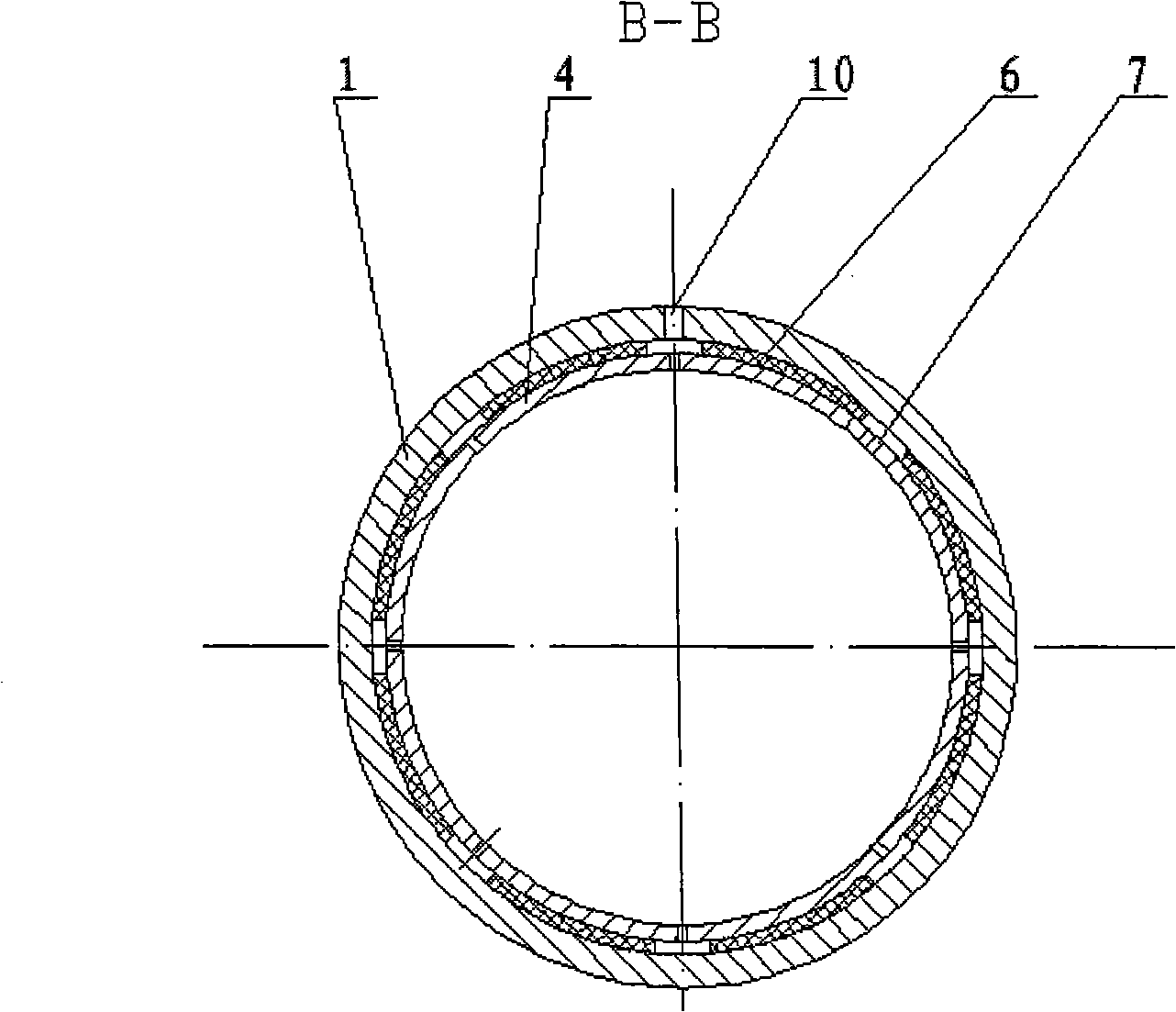
[0015] The pipeline conveying device based on the two-phase flow technology proposed by the present invention has a schematic structural diagram as shown in figure 1 shown. It includes an outer tube 1 and an inner tube 3, which are fixed by connecting screws 2. The outlet end of the air compressor or booster pump 12 is connected to the annular groove 5 through the guide pipe 11 and the guide hole 9, and the inlet pressure gauge 8 and the terminal pressure gauge 4 are respectively installed at the two ends of the outer pipe 1. The inlet end of the tube is also provided with a pressure gauge 10 for measuring the medium in the tube, and the gas entering the axial groove 7 and the circumferential groove 5 with the inlet pressure gauge installed respectively enters the inner tube through the air hole 6.

[0016] The working process of an embodiment of the device of the present invention is described below in conjunction with the accompanying drawings: after the air or low-viscosit...


PUM


Abstract

A drag reduction pipe relates to the pipeline transportation device based on the two-phase flow technology, used for transporting the fullbodied crude oil, the grease and chemically raw material, belonging to the oil gas transporting technical field, including an air (liquid) feed system, a transmission system, a monitoring system, a fixed system. Through changing the nature of friction between the medium and the wall surface, the liquid-soild friction is changed into the liquid-soild and gas-solid friction, which can make the frictional resistance reduced when the fliud with high viscosity such as crude oil, grease, and chemically raw materials are transported in the pipe, and the efficiency increased greatly. The invention has simple apparatus device, simple structure, convenient control and operation, which can reduce the wall surface resistance when the medium is transported inside the pipe, used for searching the contact of the resistance of the high viscosity medium, such as crude oil, grease, and chemically raw materials having different physical property parameters, and can be widely used in the pipe transportation industry.

Description

technical field [0001] The invention relates to a drag-reducing pipeline based on multiphase flow technology, which is used for transporting high-viscosity crude oil, oil and chemical raw materials, and belongs to the technical field of oil and gas transportation. Background technique [0002] Long-distance pipeline transportation has been listed as one of the five major transportation industries (railway transportation, road transportation, waterway transportation, air transportation and pipeline transportation). Due to the obvious advantages of pipeline transportation: large transportation volume, easy management, easy automation, low energy consumption, low freight, small land occupation, basically not affected by bad weather, safe airtight, small evaporation loss, good for environmental protection, etc. In long-distance pipeline transportation, due to the influence of temperature and its own composition, crude oil, especially high-viscosity condensable crude oil, will de...

Claims


Application Information

Patent Timeline
Patent Type & Authority Applications(China)
IPC IPC(8): F17D1/08
Inventor 王树立史小军赵会军李恩田周诗车赵书华
Owner JIANGSU POLYTECHNIC UNIVERSITY
Learn More