Relief valve for heavy equipment

A technology for heavy equipment and safety valves, applied in safety valves, mechanical equipment, balance valves, etc., can solve problems such as hydraulic fluid leakage, O-ring 15 damage, etc.

Inactive Publication Date: 2008-10-01
VOLVO CONSTR EQUIP HLDG (SWEDEN) AB
View PDF1 Cites 6 Cited by
  • Summary
  • Abstract
  • Description
  • Claims
  • Application Information

AI Technical Summary

Problems solved by technology

[0015] At this time, the O-ring 15 may be damaged due to incomplete contact with the contact surface
Hydraulic fluid may leak during operation of the safety valve due to damaged O-ring 15

Method used


Image

  • Relief valve for heavy equipment
  • Relief valve for heavy equipment
  • Relief valve for heavy equipment

Examples


Embodiment Construction

[0026] Hereinafter, preferred embodiments of the present invention will be described with reference to the accompanying drawings. The contents defined in the description, such as detailed structures and parts, are just specific details provided to help those of ordinary skill in the art fully understand the present invention, and thus the present invention is not limited thereto.

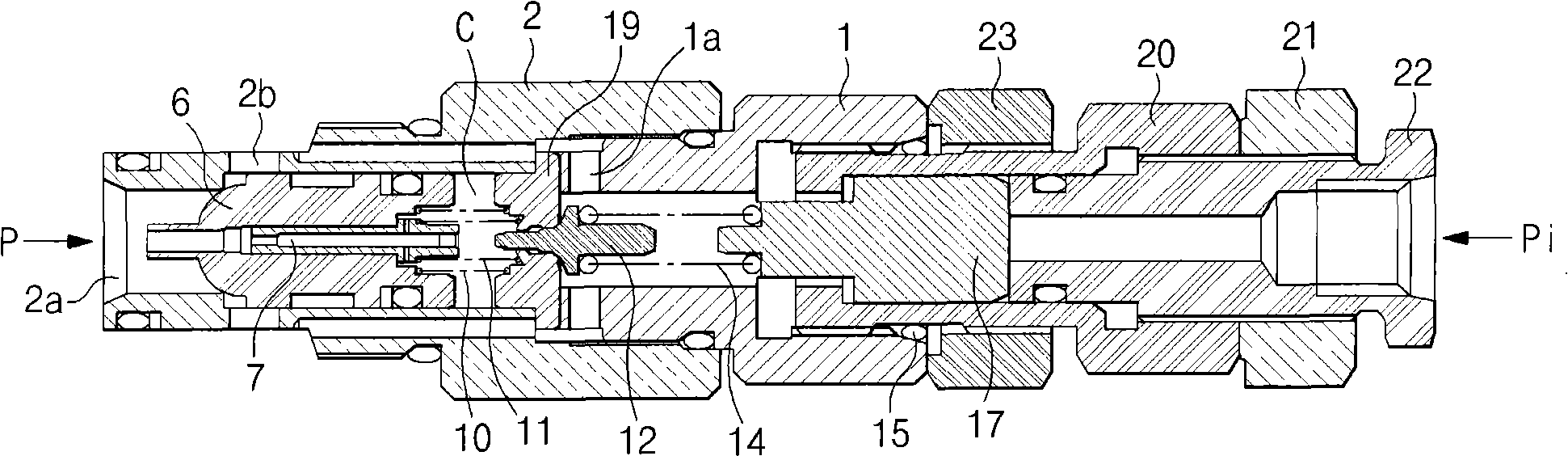
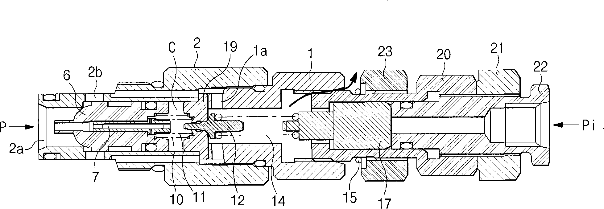
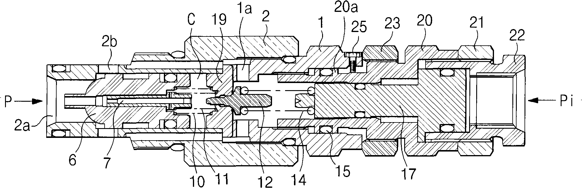
[0027] Such as Figures 3 to 5 As shown, the safety valve for heavy equipment according to the embodiment of the present invention includes a sleeve 2 having an inlet 2a formed thereon so that the inflow of hydraulic fluid from a hydraulic pump P passes through the inlet, and A tank flow passage 2b formed in the sleeve to return the hydraulic fluid in the inlet 2a to the hydraulic tank; a poppet valve 6, which is engaged inside the sleeve 2, for opening / closing the connection between the inlet 2a and the tank flow passage 2b The flow path between; the valve plate 19, which is installed opposite to ...


PUM


Abstract

A relief valve for heavy equipment is provided, which can prevent leakage of oil due to a secession of a guide that is released when pressure is set in order to re-set the set pressure of a relief valve for maintaining a set pressure of a hydraulic circuit, and can prevent damage of an O-ring mounted to seal a gap between contact surfaces. The relief valve includes a sleeve having an inlet port and a tank flow path, a poppet for opening / closing a flow path between the inlet port and the tank flow path, a valve sheet for forming a set pressure in a pressure chamber of the sleeve, a pilot poppet for draining the hydraulic fluid in the pressure chamber to the hydraulic tank; a plug screw-engaged inside the sleeve and having a tank inlet formed thereon; a guide screw-engaged inside the sleeve and having an O-ring for sealing a gap between contact surfaces with the plug and a step portion formed on the outer surface thereof; a main piston for variably controlling the set pressure in the pressure chamber; a control plug for receiving an inflow of the pilot signal pressure; and a stopper for preventing a secession of the guide from the plug.

Description

[0001] Cross References to Related Applications [0002] This application is based on and claims priority from Korean Patent Application No. 10-2007-29683 filed with the Korean Intellectual Property Office on March 27, 2007, the entire disclosure of which is incorporated herein by reference. technical field [0003] The present invention relates to a safety valve for heavy equipment capable of preventing leakage of oil and damage of an O-ring when setting pressure to reset a set pressure of the safety valve to maintain the set pressure of a hydraulic circuit. [0004] More particularly, the present invention relates to a safety valve for heavy equipment capable of preventing leakage of oil and components installed in a sleeve due to disengagement of a loosened guide when setting the pressure of the safety valve loss and can prevent damage to O-rings installed to seal gaps between contacting surfaces. Background technique [0005] The safety valve is used to maintain the pre...

Claims


Application Information

Patent Timeline
Patent Type & Authority Applications(China)
IPC IPC(8): F16K17/06F15B13/02
CPCG05D16/18F16K17/065F16K17/10G05D16/187Y10T137/7747F15B13/00F15B13/02
Inventor 田万锡姜敏爀
Owner VOLVO CONSTR EQUIP HLDG (SWEDEN) AB
Why Eureka
Try Eureka