Cam disc for a shedding mechanism of a loom

A technology of cams and looms, which is applied to cam opening mechanisms, textiles, jacquard machines, etc., can solve troublesome and expensive problems, and achieve the effects of avoiding vibration and wear, and reducing force and load

Inactive Publication Date: 2011-06-01
GROZ BECKERT KG
View PDF1 Cites 0 Cited by
  • Summary
  • Abstract
  • Description
  • Claims
  • Application Information

AI Technical Summary

Problems solved by technology

This shuttle is relatively laborious and expensive

Method used


Image

  • Cam disc for a shedding mechanism of a loom
  • Cam disc for a shedding mechanism of a loom
  • Cam disc for a shedding mechanism of a loom

Examples


Embodiment Construction

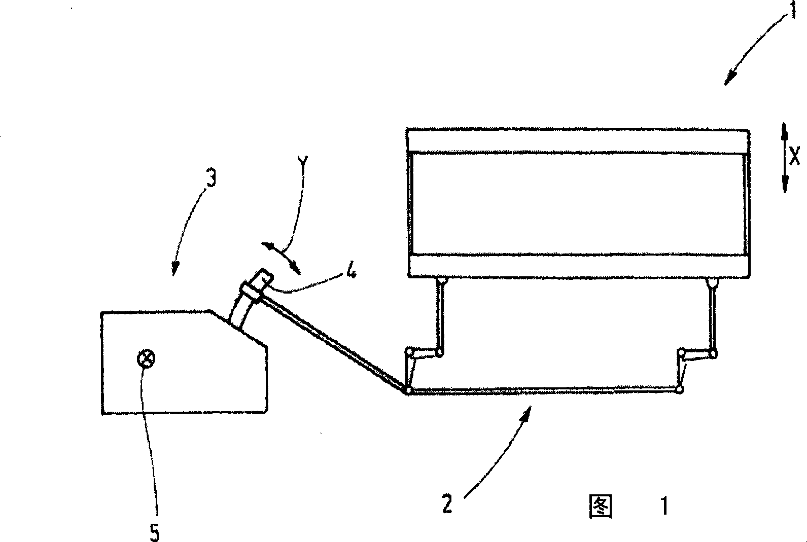
[0021] FIG. 1 shows a heald frame 1 which is driven by an eccentric device 3 via a connecting rod 2 in a vertically oscillating manner. The vertical direction indicated by the arrow is called the X direction. At its output, the eccentric device 3 has a rocker arm 4 which is connected to the connecting rod 2 . The rocker arm 4 executes a reciprocating vibrational movement, indicated by the arrow y in FIG. 1 , which is derived from the rotation of the main shaft 5 . The spindle is equipped with a drive, such as an electric motor, and rotates at a substantially constant rotational speed.

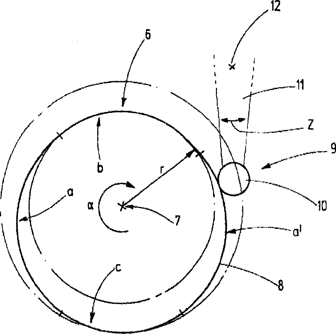
[0022] one such as figure 2 The cam 6 shown is located on the main shaft 5 . Its center of rotation 7 is determined by the main shaft 5 . It has a circumferential surface 8 whose radius r to the center of rotation 7 depends on the angle of rotation α. A cam follower 9 , for example in the form of a roller 10 bearing against the peripheral surface 8 , is supported by a rocker 11 . This roc...


PUM


Abstract

A preferable eccentric apparatus (3) comprises a cam (6), with a circumference face (8) for determining various laws of motion with various sectors, which uses the law of motion in a primary motion state (a) and a final state (b, c) where the heald frame is possible to passes through less part of the motion thereof, and it is best that the part is less than 50% of the whole motion or the whole travel route, so as to determine the law of motion of the cam (6) in various motion sate or sector, to make a first derivative identical with a second one of the law of the motion for adjacent sectors in a transit site.

Description

technical field [0001] The invention relates to a cam for an eccentric device and to such an eccentric device. Background technique [0002] To form the shed, a plurality of heald frames are usually used on looms, each having a plurality of healds arranged parallel to one another, through which the warp threads are guided through the yarn eyes. In order to form the shed, the heald frame is moved up and down rapidly. Shuttle drives are used for this, they are called shuttles or eccentric devices. In this case, the eccentric device generates an oscillating reciprocating movement from the rotational movement of the drive shaft, which leads to a vertical movement of the heald frame. High weaving speeds can be achieved. [0003] When the heald frame moves up and down, there are high dynamic loads on the heald frame, its parts, the weaving healds, the shuttle and the connecting rods between the heald frame and the dobby. [0004] DE 10343377 discloses a dobby in which individu...

Claims


Application Information

Patent Timeline
Patent Type & Authority Patents(China)
IPC IPC(8): D03C5/00F16H53/00
CPCD03C3/36D03C5/04
Inventor B・芒斯特F・梅特勒
Owner GROZ BECKERT KG
Why Eureka
Try Eureka