
Large field longitudinal surface magnetooptical Kerr effect measuring apparatus

A technology of magneto-optical Kerr effect and measuring device, applied in the field of optical technology measurement, can solve problems such as increasing the difficulty of research work, difficulty in measuring magnetic properties, etc.

Inactive Publication Date: 2008-09-24
FUDAN UNIV
View PDF0 Cites 32 Cited by
  • Summary
  • Abstract
  • Description
  • Claims
  • Application Information

AI Technical Summary

Problems solved by technology

However, the high coercive force (5KOe--15KOe) of FePt-based thin film media makes it difficult to measure its magnetic properties. For the hysteresis loop along the vertical direction, it can be measured by the polar Kerr effect; The hysteresis loop in the direction can only be measured with a high-sensitivity vibrating sample magnetometer
This undoubtedly increases the difficulty of the research work

Method used


Image

  • Large field longitudinal surface magnetooptical Kerr effect measuring apparatus
  • Large field longitudinal surface magnetooptical Kerr effect measuring apparatus
  • Large field longitudinal surface magnetooptical Kerr effect measuring apparatus

Examples


Embodiment Construction

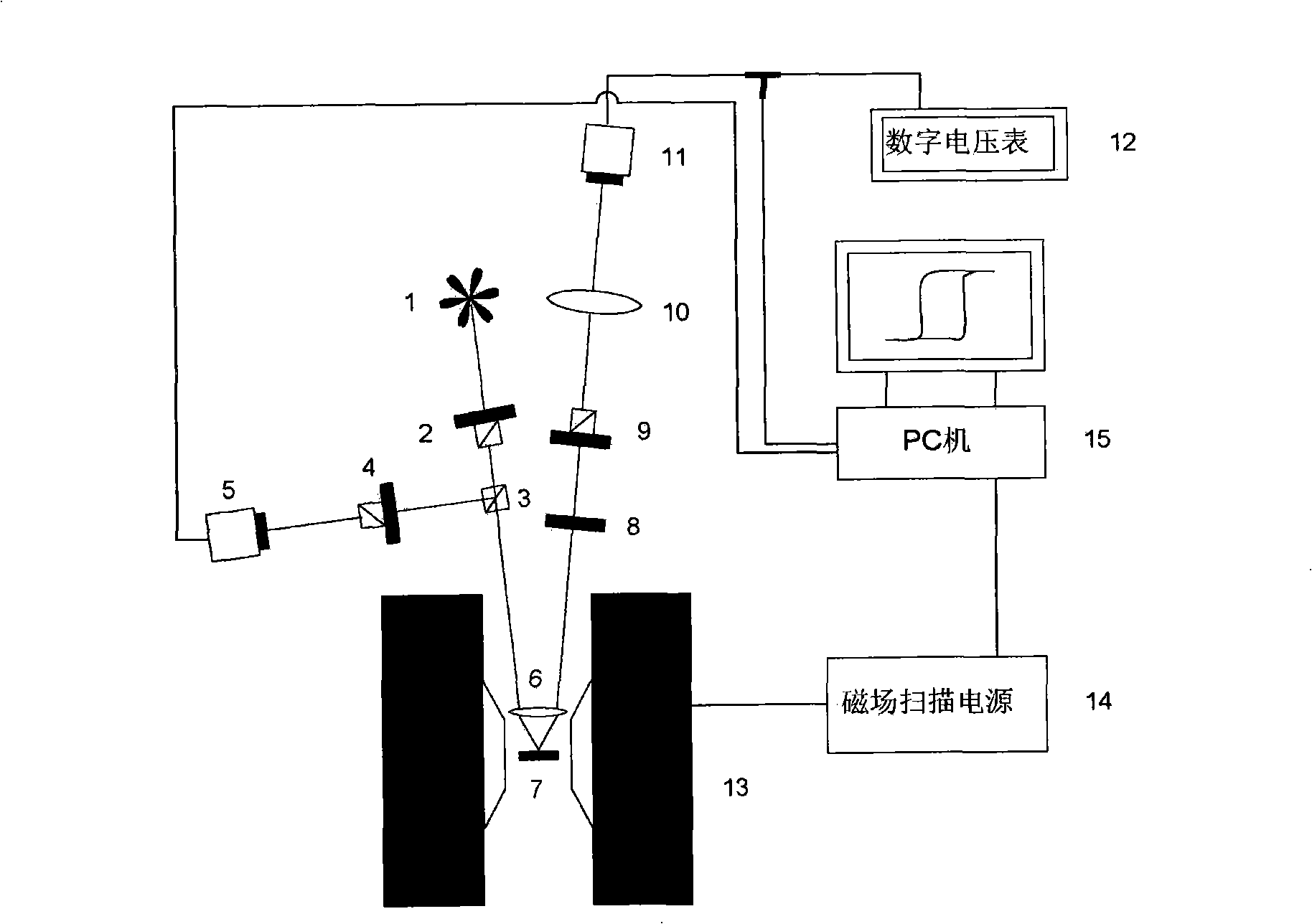
[0064] The measuring device is mainly composed of an electromagnet, a program-controlled magnet power supply, an optical system and a PC.

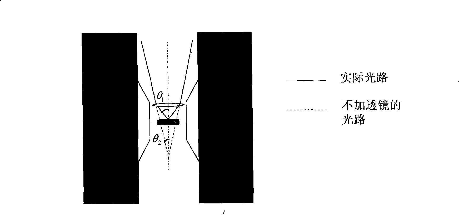
[0065] What the laser 1 adopted in the present invention is a semiconductor laser, wavelength λ=670nm, the polarization plane of the laser after passing through the polarizing prism 2 is parallel to the incident plane, that is, incident with p light. In order to increase the incident angle, a convex lens 6 is added in front of the sample. The focal length of the convex lens 6 is about 4 cm, and the diameter is 3 cm. The distance between the convex lens 6 and the sample holder is between 3.5 and 5.0 cm. The lens frame is processed with copper and aluminum to ensure the stability of the lens frame under the magnetic field, and the bottom is embedded with a magnetic disk to be fixed on the electromagnet 13. The sample holder is also made of copper and aluminum, fixed on the large electromagnet in a suspended manner, and can fine-tune the posi...


PUM

PropertyMeasurementUnit
Diameteraaaaaaaaaa
Focal lengthaaaaaaaaaa

Abstract

The invention belongs to the optical technical field, in particular to a measuring device of magneto-optical kerr effect on longitudinal surface of a large field. The device consists of an electromagnet, a program control magnet power supply, a light path system and an operation control system (PC), wherein, the light path system subsequently consists of a semiconductor laser, a polarizing prism, a half transparent and half reflecting prism, a polarization detecting prism, a photodetector, a convex lens, a sample holder, an aperture, another polarization detecting prism, a long focal length convex lens and another photodetector; a magnetic filed for measurement is provided by the electromagnet which can provide a magnetic filed up to 1.5 tesla when the magnetic pole spacing is 4cm. The invention uses a converging convex lens to effectively expand the incident angle and the reflection angle of the light on the surface of the a sample, overcome the restriction of the magnetic pole spacing to the incident angle of the laser and enhance the magneto-optical kerr signal intensity on the longitudinal surface. The invention makes measurement of the high-coercivity magnetic film by the magneto-optical kerr effect possible.

Description

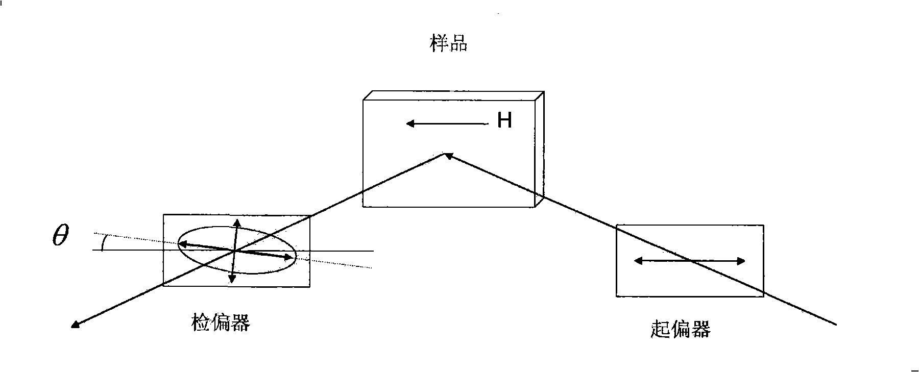
technical field [0001] The invention belongs to the field of optical technology measurement, in particular to a large-field longitudinal surface magneto-optical Kerr effect measurement device. technical background [0002] In 1877, John Kerr discovered the magneto-optical Kerr effect. According to the difference between the magnetization vector of the sample relative to the laser incident surface and the sample surface, the magneto-optic Kerr effect can be divided into three types: longitudinal Kerr effect, polar Kerr effect and transverse Kerr effect [1]. In 1985, Moog and Bader conducted magneto-optical Kerr effect measurements on ferromagnetic ultra-thin films, and successfully obtained the hysteresis loop of a magnetic material with a thickness of one atomic layer [2]. Since the measurement sensitivity of this method can reach the thickness of an atomic layer, it has become an important method for the study of surface magnetism. [0003] The following takes the longitu...

Claims


Application Information

Patent Timeline
IPC IPC(8): G01N21/21G01R33/14
Inventor 马斌顾培培张宗芝金庆原
Owner FUDAN UNIV
Learn More