Cantilever driving frame head posture measuring systems and its method
A technology of cantilever roadheader and measurement system, which is applied in the field of heading head, can solve the problems of poor forming quality of roadway excavation section, achieve the effect of improving forming quality and driving speed, reducing labor intensity, and high accuracy of position and posture measurement
- Summary
- Abstract
- Description
- Claims
- Application Information
AI Technical Summary
Problems solved by technology
Method used
Image
Examples
Embodiment 1
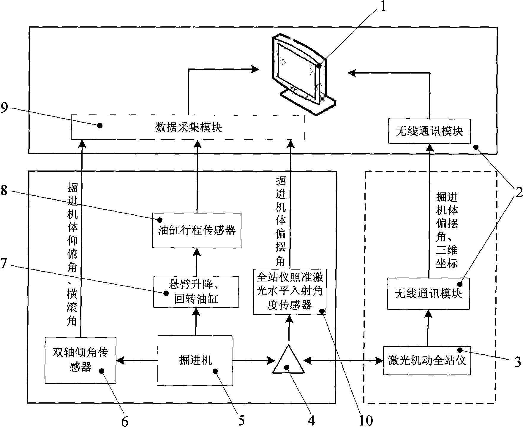
[0021] Such as figure 1 and Figure 5 As shown, the pose measurement system of the cantilever heading machine head consists of the cantilever lifting cylinder 9 of the cantilever roadheading machine 8, the cantilever rotary cylinder 10, the telescopic cylinder 11 of the heading machine head, the cylinder stroke sensor 12, the laser motorized total station 3, and the reflecting prism 4 , a wireless communication module 2, a vehicle body yaw angle sensor 5, a biaxial inclination sensor 7, a data acquisition module 13 and a computer 1.
[0022] 1) A laser mobile total station 3 is installed on the roadway wall that has been excavated behind the body of the roadheader 8, is at the same level as the rear bracket 6 of the roadheader 8, and is between 1 meter and 10 meters away from the body of the roadheader 8 and measure the three-dimensional coordinates and attitude angle of the installation platform in the geodetic coordinate system, install the laser motorized total station 3 o...
Embodiment 2
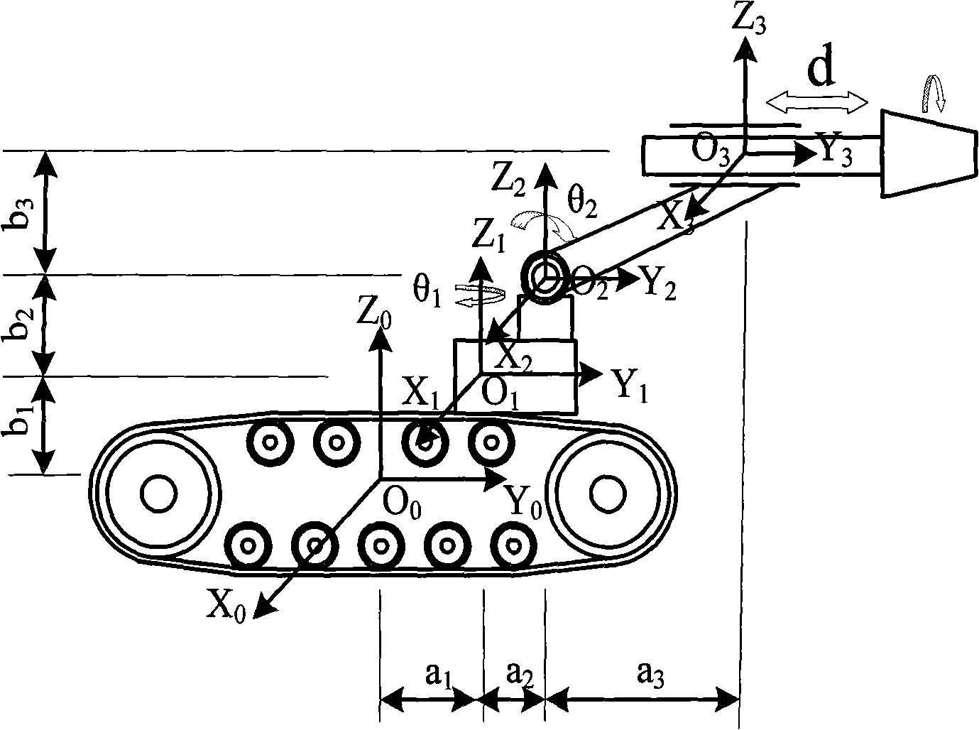
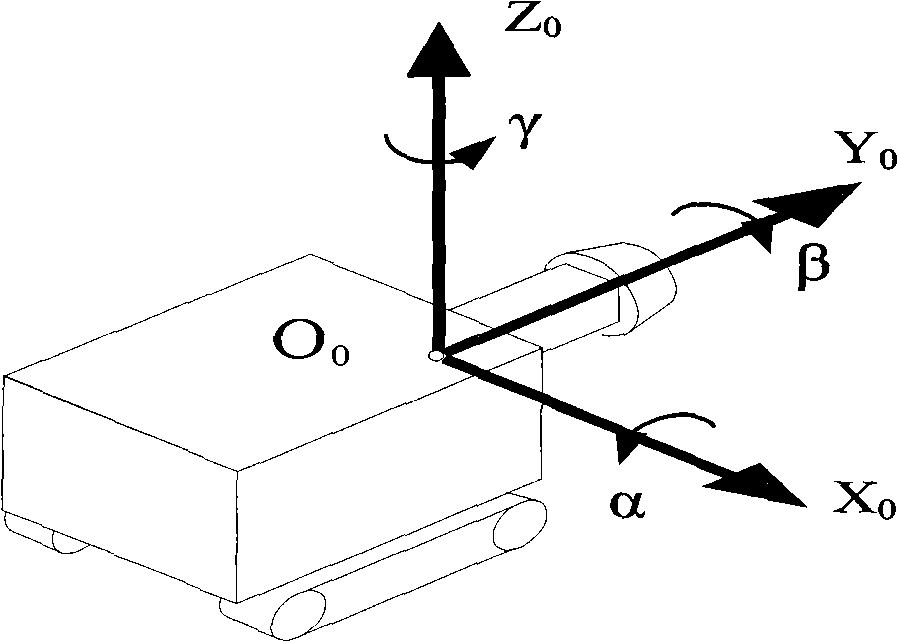
[0030] Such as figure 2 and Figure 4 As shown, the solution to the measurement method of the cantilever heading machine head pose is to establish the earth coordinate system OXYZ, the measurement coordinate system O c x c Y c Z c , The body coordinate system O of the excavation locomotive 0 x 0 Y 0 Z 0 , cantilever rotary joint coordinate system O 1 x 1 Y 1 Z 1 , cantilever lifting joint coordinate system O 2 x 2 Y 2 Z 2 , Tunneling head telescopic joint coordinate system O 3 x 3 Y 3 Z 3 and roadway section coordinate system O h x h Y h Z h , each coordinate system is connected in series to form a space coordinate transformation dimension chain.
[0031] figure 2 The body coordinate system of the roadheader and the coordinate system of the cantilever joint are established on the simplified model of the roadheader system shown. θ1, θ2, and d are the variables of the rotary joint, lifting joint, and telescopic joint of the roadheader’s cantilever, respe...
PUM
 Abstract
Description
Claims
Application Information
 - R&D
- Intellectual Property
- Life Sciences
- Materials
- Tech Scout
- Unparalleled Data Quality
- Higher Quality Content
- 60% Fewer Hallucinations
Browse by: Latest US Patents, China's latest patents, Technical Efficacy Thesaurus, Application Domain, Technology Topic, Popular Technical Reports.
© 2025 PatSnap. All rights reserved.Legal|Privacy policy|Modern Slavery Act Transparency Statement|Sitemap|About US| Contact US: help@patsnap.com


