Rotor engine
A rotor engine and rotor technology, applied in combustion engines, machines/engines, internal combustion piston engines, etc., to achieve the effects of simple structure, fuel saving, and low center of gravity
Inactive Publication Date: 2010-11-10
刘若丹
View PDF3 Cites 0 Cited by
- Summary
- Abstract
- Description
- Claims
- Application Information
AI Technical Summary
Problems solved by technology
The purpose of the present invention is to provide a rotary engine, which fundamentally solves the problems of valve timing and valve stroke in the existing piston cam valve engine, so that the valve opening can reach 100% of the cylinder bore, and the stroke force can be completely used in the engine. The power output of the rotor can greatly save fuel, and under the condition of a certain total cylinder volume, the compression ratio of the engine can be increased, the power and combustion efficiency of the piston engine can be exerted, and the quality of exhaust gas emission can be improved; the engine structure is simpler and more compact. smaller
Method used
View moreImage
Smart ImageViewing Examples


Examples
Embodiment Construction
Login to View More PUM
 Abstract
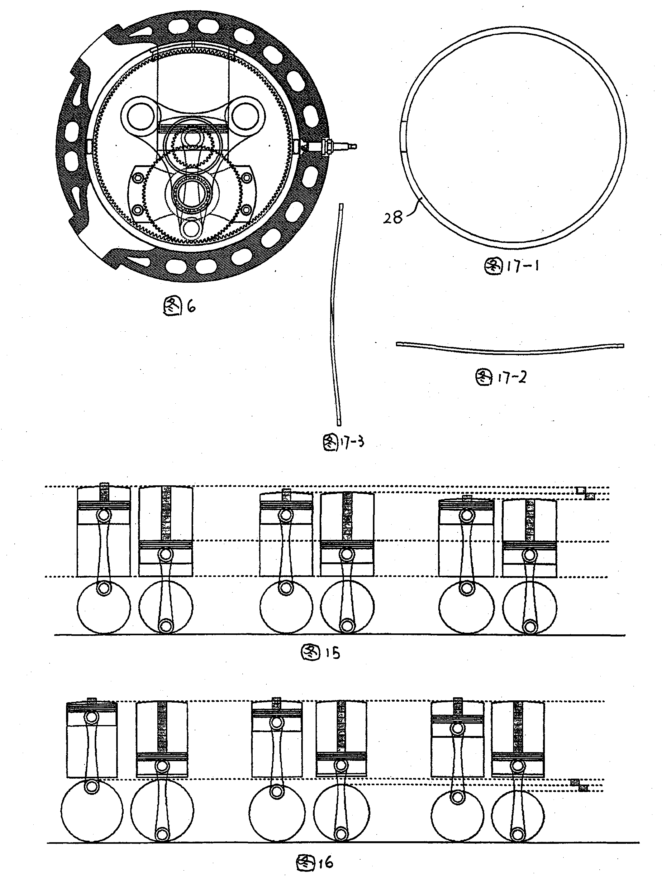
The invention relates to a rotor engine, which belongs to a rotation piston-type engine, and comprises a stator assembly and a rotor assembly; an inlet and an exhaust are arranged with an interval of 90 degree on the stator, and a spark plug hole is arranged at the midpoint between the inlet and the exhaust; the rotor assembly comprises a rotor body, a rotor spindle and a bent axle; a cylinder hole, a piston and a connecting bar are arranged along a radial direction in the rotor body; through a bearing, the bent axle is installed on a hole of a horizontal bent axle; a crank of the bent axle and the piston connecting bar are connected; two bent axle gears on the bent axle are meshed respectively with two internal gear rings in an inner cavity of the stator, wherein the transmission ratio of the two internal gear rings is 1:2; spindles of two rotors are installed on the left and the right end covers of the stator; the two spindles are set and connected on the rotor body; a gas sealing mechanism is arranged on the cylinder hole. Problems of valve timing and valve stroke are solved fundamentally by a distribution system; the rotation piston type engine is characterized in simple structure, smaller volume, and high compression ratio.
Description
rotary engine technical field The invention relates to the field of manufacture of internal combustion engines, in particular rotary piston engines, ie rotary engines. Background technique The traditional reciprocating piston engine has a development history of more than 100 years. It has been developed to the widely used piston cam valve engine now. Performance and durability have been quite mature. However, in today's global warming crisis and energy shortage, the use of a very large amount of automobile engines and other forms of internal combustion engines is one of the important reasons for these crises. Higher requirements are put forward, and these requirements have the following problems to be solved for the piston cam valve engine: 1. Valve opening problem: valve opening and its related valve timing and valve stroke. The valve opening refers to the maximum opening of the exhaust valve or intake valve. The valve opening of the existing traditional piston cam v...
Claims
Login to View More Application Information
Patent Timeline
 Patent Type & Authority Patents(China)
IPC IPC(8): F02B53/02F02B55/16F02B55/02F02B53/14F02B55/10
CPCY02T10/17Y02T10/12
Inventor 刘若丹
Owner 刘若丹
Features
- R&D
- Intellectual Property
- Life Sciences
- Materials
- Tech Scout
- Unparalleled Data Quality
- Higher Quality Content
- 60% Fewer Hallucinations
Learn More Browse by: Latest US Patents, China's latest patents, Technical Efficacy Thesaurus, Application Domain, Technology Topic, Popular Technical Reports.
© 2025 PatSnap. All rights reserved.Legal|Privacy policy|Modern Slavery Act Transparency Statement|Sitemap|About US| Contact US: help@patsnap.com