
Interlocking device of grounding switch and front lower door in switch cabinet and switch cabinet

A technology of interlocking device and grounding switch, applied in the direction of grounding device, grounding device, switching device and other directions of switchgear, can solve problems such as poor safety, and achieve the effects of simple structure, increased contact area of ​​jacking, and good reliability

Active Publication Date: 2021-03-16
HENAN PINGGAO GENERAL ELECTRIC CO LTD +2
View PDF17 Cites 1 Cited by
  • Summary
  • Abstract
  • Description
  • Claims
  • Application Information

AI Technical Summary

Problems solved by technology

[0006] The purpose of the present invention is to provide an interlocking device between the grounding switch and the front lower door in the switch cabinet to solve the problem in the prior art that the grounding switch can still be opened when the front lower door of the switch cabinet is not closed; Another object is to provide a switchgear to solve the problem of poor safety in the existing switchgear due to the fact that the grounding switch can still be opened when the front lower door is not closed

Method used


Image

  • Interlocking device of grounding switch and front lower door in switch cabinet and switch cabinet
  • Interlocking device of grounding switch and front lower door in switch cabinet and switch cabinet
  • Interlocking device of grounding switch and front lower door in switch cabinet and switch cabinet

Examples


Embodiment 1

[0103] Such as figure 2 with image 3 As shown, it mainly includes a device seat 1, a limit rod push rod 2, a push rod clamp plate 3 and a clamp push plate 4. The device seat 1 is a fixed base plate for fixing to the cabinet body of the switch cabinet. The fixed base plate includes an upper plate body 5, a lower plate body 6 and a connecting plate body 7. The upper plate body 5 and the lower plate body 6 are arranged in parallel, and the connecting plate body The body 7 is connected between the upper plate body 5 and the lower plate body 6; the limit rod push rod 2 is movable and arranged on the device seat 1 along the up and down direction through the clamp guide seat 19, and has the ability to move upward under the action of the corresponding elastic structure. Trend: the ejector pin clamp 3 is oriented in the horizontal direction, and is adapted to the limit rod ejector rod 2, and is used to limit the up and down movement of the limit rod ejector rod 2 and release the res...


PUM


Abstract

The invention relates to an interlocking device of a grounding switch and a front lower door in a switch cabinet and the switch cabinet. The interlocking device comprises a limiting rod ejector rod and a clamping plate pushing piece; the limiting rod ejector rod has an upward movement trend under the action of a corresponding elastic structure; the limiting rod ejector rod is provided with a blocking position and a receding position in the moving stroke, and the blocking position corresponds to the upper end of the moving stroke of the limiting rod ejector rod and is used for blocking the vertical limiting rod on the switch cabinet from moving downwards; a limiting groove is formed in the outer circumferential face of the limiting rod ejector rod, an ejector rod bayonet is formed in the side, close to the limiting rod ejector rod, of an ejector rod clamping plate, and the ejector rod bayonet is used for being clamped into the limiting groove to limit downward movement of the limiting rod ejector rod when the limiting rod ejector rod is located at the blocking position; and the clamping plate pushing piece is used for pushing the ejector rod clamping plate under the driving of the front lower door when the front lower door is closed, so that the limitation of the ejector rod bayonet in the ejector rod clamping plate on the limiting rod ejector rod is relieved. According to the scheme, the problem that in the prior art, when the front lower door of the switch cabinet is not closed, the grounding switch can still be switched off is solved.

Description

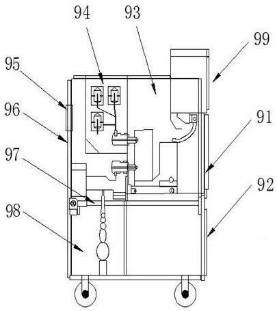
technical field [0001] The invention relates to an interlocking device between a grounding switch and a front lower door in a switch cabinet and a switch cabinet. Background technique [0002] The switchgear is an important equipment in the power system. The existing switchgear, such as a switchgear with front and rear interlocking disclosed in the Chinese patent document with the authorized announcement number CN206225807U, has a structure such as figure 1 As shown, the front side of the upper end of the switchgear body 99 is provided with a control unit chamber 93, and the rear side of the upper end of the switchgear body 99 is provided with a busbar chamber 94 and a rear upper door 96, and the rear upper door 96 is hinged with the switchgear body 99 through the rear door interlock 95 The lower rear side of the switch cabinet body 99 is provided with a cable chamber 98, the lower front side of the switch cabinet body 99 is provided with a front lower door 92, and a front d...

Claims


Application Information

Patent Timeline
Patent Type & Authority Applications(China)
IPC IPC(8): H01H9/22H01H31/06H02B1/16H02B1/30H02B1/32H02B11/133H02B11/28
CPCH01H31/06H01H9/22H01H9/226H02B1/16H02B1/30H02B1/32H02B11/133H02B11/28
Inventor 田凤雷王焕李铁关红伟周凯张二勇弓腾飞郭忠贺王春生朱向宇田红超叶思远李康康张弦飞张军邢东晓
Owner HENAN PINGGAO GENERAL ELECTRIC CO LTD
Learn More