Optical products storing container

A technology for optical products and containers, which is applied in the field of optical product storage containers, can solve the problems that cannot be solved, the lateral sliding amount of the container body 101 becomes larger, and the practicality of the storage container disappears, so as to achieve the effect of preventing collapse

Inactive Publication Date: 2011-06-08
KONICA MINOLTA OPTO
View PDF1 Cites 0 Cited by
  • Summary
  • Abstract
  • Description
  • Claims
  • Application Information

AI Technical Summary

Problems solved by technology

[0009] The above problems even if for example Image 6 (a)~ Image 6 Changing the thickness of the sheet-like resin material forming the container body 101 and the lid member 102 as shown in (c) cannot solve the problem.
[0010] On the other hand, when the container body support portion 122 is extended outward to prevent collapse and the width is formed wide, the body side tapered portion 111 and the lid side tapered portion 123 cannot be fitted to ensure the airtightness inside the container 100, Loss of utility as optical storage container
If the container body support portion 122 is expanded inwardly to form a wide width, the distance between the outer peripheral surface of the upright portion 121 and the inner peripheral surface of the body side taper portion becomes wider, and the positioning of the upper side container body 101 cannot be performed. , the lateral sliding amount of the container body 101 becomes large, and the collapse cannot be prevented

Method used


Image

  • Optical products storing container
  • Optical products storing container
  • Optical products storing container

Examples


Embodiment Construction

[0069] Embodiments of the present invention will be described below with reference to the drawings.

[0070] First, the optical product storage container (hereinafter referred to as container) of the present invention will be described.

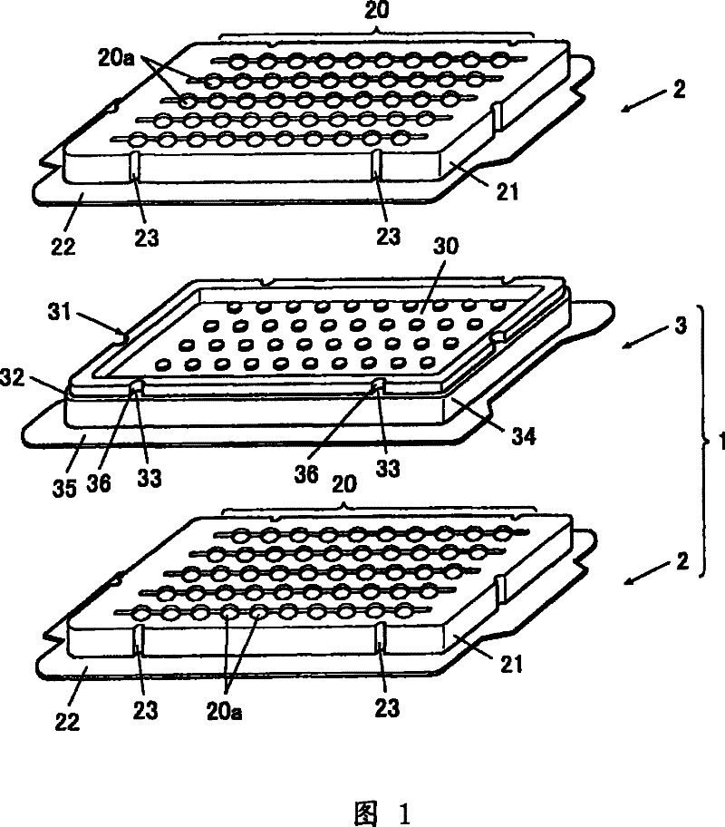
[0071] figure 1 It is an exploded perspective view of the container 1 of the first embodiment of the present invention.

[0072] As shown in the figure, the container 1 accommodates optical products (not shown) and can be stacked in multiple layers, and includes a container body 2 and a lid member 3 that are substantially rectangular in plan view.

[0073] These container body 2 and lid member 3 are formed by vacuum forming a sheet-like resin material and have flexibility. The thickness of the sheet-like resin material in this embodiment is 0.3-0.5 mm.

[0074] Among these container main body 2 and cover member 3, the container main body 2 has the product placement part 20 in the center. The product placement part 20 has a plurality of r...


PUM


Abstract

Optical product holding container, the container body (2) of the container (1) has body side pyramis (21) drooping from the product placing part (20) and surrounding the circumference of the product placing part (20), body side flange part (22) for surrounding the peripheral flange and supporting the cover part (3), body side recessing part (23) for recessing from the outer periphery. The cover part has container supporting part (32) which surrounds the periphery of the cover part (30) and supports the inner peripheral edge of the body side flange part (22) of other containers body (2) at theupper layer side, standing part (31) protruding upwards between the cover part (30) and the container body supporting part (32) to surround the cover part (30), cover side recessing side (36) recessing from the outer periphery of the standing part (31), container body supporting assist part (33) under the body side recessing part (23) formed by the cover side recessing side (36) and supporting the other containers body (2), cover side pyramis (34) drooping from the outer periphery of the container body supporting part (32), cover side flange part (35) for surrounding the peripheral flange andbeing supported by the body side flange part (22).

Description

technical field [0001] The present invention relates to an optical product storage container for storing optical products. Background technique [0002] Conventionally, optical products such as lenses are stored and transported in highly airtight containers that can be stacked in multiple layers (for example, refer to Patent Document 1). [0003] For example image 3 , Figure 4 As shown, such a container 100 includes a flexible container body 101 and a lid member 102 formed by vacuum forming a sheet-like resin material. [0004] Wherein the container body 101 has: a product placement part 110 provided with a plurality of concave parts 110a for placing optical products; The main body side flange part 112 of the cover member 102 disposed on the periphery of the part 111 is supported. [0005] On the other hand, the lid member 102 has: a cover part 120 covering the product placement part 110 from above, and standing up from the periphery of the cover part 120 to be arranged...

Claims


Application Information

Patent Timeline
Patent Type & Authority Patents(China)
IPC IPC(8): B65D85/00B65D85/30B65D71/70B65D21/032B65D43/02
Inventor 伊藤京一
Owner KONICA MINOLTA OPTO
Why Eureka
Try Eureka