Non-oriented electrical steel head and tail flash welding technique

A technology of grain-oriented electrical steel and process method, applied in the field of non-oriented electrical steel head and tail flash welding, can solve the problems of electrical steel welding seam easily broken belt, high maintenance technical requirements, deterioration of welding seam performance, etc., and achieve good plasticity and toughness. , no overlap phenomenon, the effect of improving the quality of the weld

Inactive Publication Date: 2010-09-08
PANZHIHUA IRON & STEEL RES INST OF PANGANG GROUP +1
View PDF0 Cites 0 Cited by
  • Summary
  • Abstract
  • Description
  • Claims
  • Application Information

AI Technical Summary

Problems solved by technology

Silicon is one of the main elements that can significantly increase the cold hardening index. Under the condition of 0.2% to 1.5%wt of silicon, the hardness of the weld seam will greatly increase and become brittle when it is deformed by high-speed cold rolling, which will deteriorate the weld. Seam performance, resulting in electrical steel welds are more likely to break
[0003] However, in the prior art, for the head-to-tail welding of the strip steel in the combined cold-rolling-acid-rolling unit, a laser welding process is used to improve the mechanical properties of the weld seam so that it is basically consistent with the base metal and reduce broken strips, but the cost is high , high maintenance technical requirements, generally used in high-silicon oriented silicon steel production lines containing more than 1.5% silicon

Method used


Image

  • Non-oriented electrical steel head and tail flash welding technique
  • Non-oriented electrical steel head and tail flash welding technique
  • Non-oriented electrical steel head and tail flash welding technique

Examples


Embodiment 1

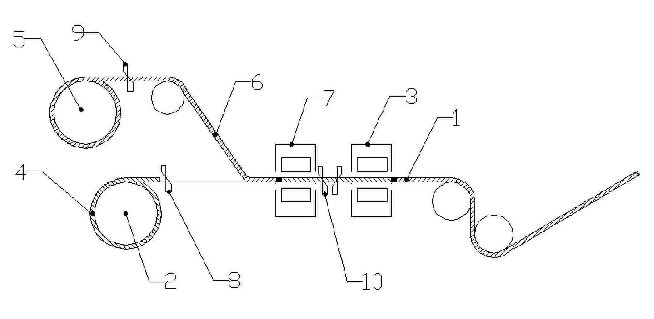
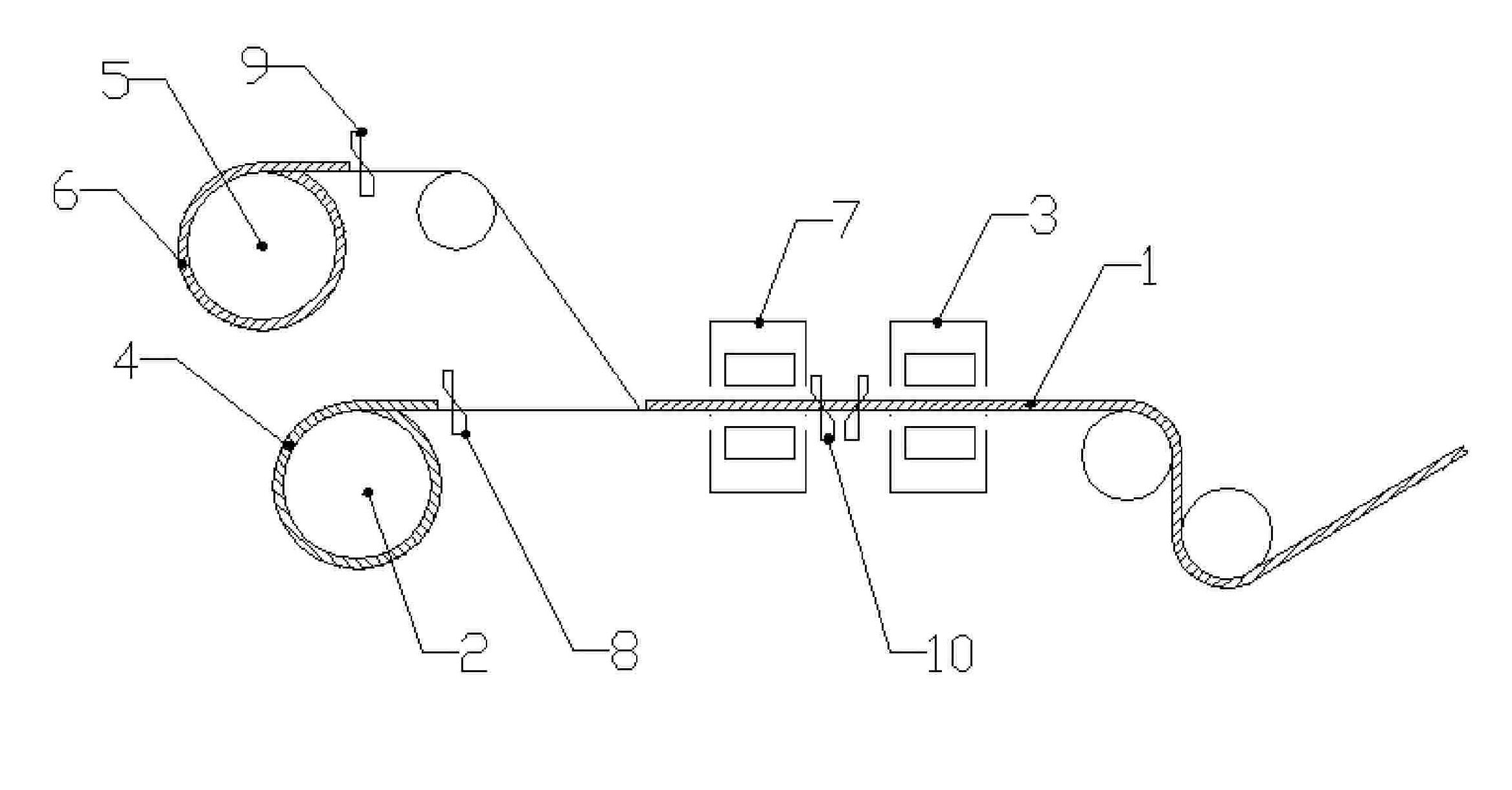
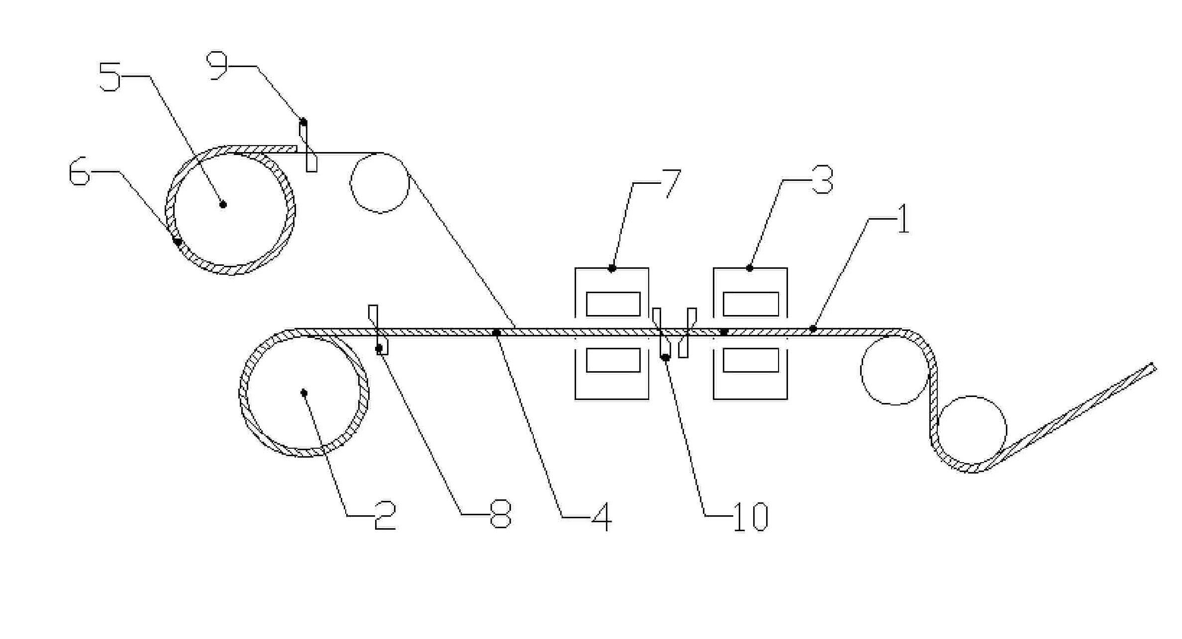
[0033] Example 1: In the combined cold-rolling and acid-rolling unit, the current coil of non-oriented electrical steel 1 enters the acid tank, and after the tail leaves the first coiling position 5, the rear coil of non-oriented electrical steel 6 is placed at the first coiling position 5 , the DX series low-carbon and low-silicon steel series steel 4 of the same thickness and width are placed on the second winding position 2, and the low-carbon and low-silicon steel series steel 4 can be reciprocated forward and backward at the second winding position 2. Return materials. After the tail of the pre-rolled non-oriented electrical steel 1 that has entered the acid tank and the head of the low-carbon and low-silicon steel series steel 4 of the DX series complete the first flash welding, the low-carbon and low-silicon steel series steel 4 at the second winding position 2 Drive the welded seam back to the electrode 7 side of the movable end of the welding machine, the shear knife ...

Embodiment 2

[0034] Example 2: In the combined cold-rolling and acid-rolling unit, the current coil of non-oriented electrical steel 1 enters the acid tank, and after the tail leaves the first coiling position 5, the rear coil of non-oriented electrical steel 6 is placed at the first coiling position 5 , IF series low-carbon and low-silicon steel series steel 4 of the same thickness and width are placed on the second winding position 2, and the low-carbon and low-silicon steel series steel 4 can be reciprocated forward and backward at the second winding position 2 Return materials. After the tail of the pre-coiled non-oriented electrical steel 1 that has entered the acid tank and the head of the low-carbon and low-silicon steel series steel 4 of the IF series complete the first flash welding, the low-carbon and low-silicon steel series steel 4 at the second winding position 2 Drive the welded seam back to the electrode 7 side of the movable end of the welding machine, the shear knife 9 cut...

Embodiment 3

[0035] Example 3: In the combined cold-rolling and acid-rolling unit, the current coil of non-oriented electrical steel 1 enters the acid tank, and after the tail leaves the first coiling position 5, the rear coil of non-oriented electrical steel 6 is placed at the first coiling position 5 The low-carbon and low-silicon steel series steel 4 of the St series with the same thickness and width is placed on the second winding position 2, and the low-carbon and low-silicon steel series steel 4 can be reciprocated forward and backward at the second winding position 2. Return materials. After the first flash welding is completed between the tail of the pre-rolled non-oriented electrical steel 1 that has entered the acid tank and the head of the low-carbon and low-silicon steel series steel 4 of the St series, the low-carbon and low-silicon steel series steel 4 at the second winding position 2 Drive the welded seam back to the electrode 7 side of the movable end of the welding machine...


PUM

PropertyMeasurementUnit
lengthaaaaaaaaaa

Abstract

The invention discloses a flash welding technological method for the head and the tail of non-oriented electrical steel used in cold-rolling pickling line and tandem cold mill to enhance the quality of the weld joint. The technological method comprises the following steps: a low-carbon steel material with the same thickness and width is inserted between a front roll of non-oriented electric steel and a back roll of non-oriented electric steel; the head of the low-carbon steel material is welded with the tail of the back roll of non-oriented electric steel and the tail of low-carbon steel material is welded with the head of the back roll of the non-oriented electric steel. The flash welding technological method for the head and the tail of a non-oriented electrical steel used in cold-rolling pickling line and tandem cold mill has the advantages that due to good plasticity and toughness, the quality of the weld joint of the non-oriented steel after welding is greatly enhanced without lap joint and is qualified in the on-site cupping test, avoiding thrust belt of the joint; the weld joint can not only pass through the acid, but also normally through the miller for rolling, without need of reducing pressure, tension or speed, therefore, the technological method is particularly suitable for popularization in band steel manufacturing of cold-rolling pickling line and tandem cold mill.

Description

technical field [0001] The invention relates to a welding process operation method, in particular to a process method for head-to-tail flash welding of non-oriented electrical steel used in the production of a combined cold-rolling-acid-rolling unit. Background technique [0002] At present, in the modern large-scale cold-rolling production process, the hot-rolled steel strip needs to be welded by a welding machine to form a whole strip before pickling, so as to ensure the continuous production of pickling and rolling. Connections are made using the fast flash soldering process. The weld at the joint of the steel strip is the biggest weak link in the cold rolling production process. When the poor quality weld passes through the rolling mill, measures such as raising the roll gap, reducing pressure and tension, and reducing the rolling speed must be taken. The cold-rolling-acid-rolling unit has higher requirements on the welding quality of the steel strip head and tail. It i...

Claims


Application Information

Patent Timeline
Patent Type & Authority Patents(China)
IPC IPC(8): B23K11/04
Inventor 李大东周一林邓菡梁英曹勇陈曙光周三宝
Owner PANZHIHUA IRON & STEEL RES INST OF PANGANG GROUP
Why Eureka
Try Eureka