
Voltage control circuit and gain-variable amplifier

A technology of voltage control circuit and gain amplifier, which is applied in the direction of gain control, improving amplifier to reduce nonlinear distortion, and amplification control, etc. It can solve problems such as abnormal output voltage and inoperable application circuit

Inactive Publication Date: 2011-08-31
PRINCETON TECH CORP
View PDF0 Cites 0 Cited by
  • Summary
  • Abstract
  • Description
  • Claims
  • Application Information

AI Technical Summary

Problems solved by technology

[0006] The purpose of the present invention is to solve the problem that the voltage control circuit traditionally applied to the variable gain amplifier circuit may cause the output voltage to be abnormal, making subsequent application circuits unable to operate, and to provide a voltage control circuit that can control the stable output voltage

Method used


Image

  • Voltage control circuit and gain-variable amplifier
  • Voltage control circuit and gain-variable amplifier
  • Voltage control circuit and gain-variable amplifier

Examples


Embodiment Construction

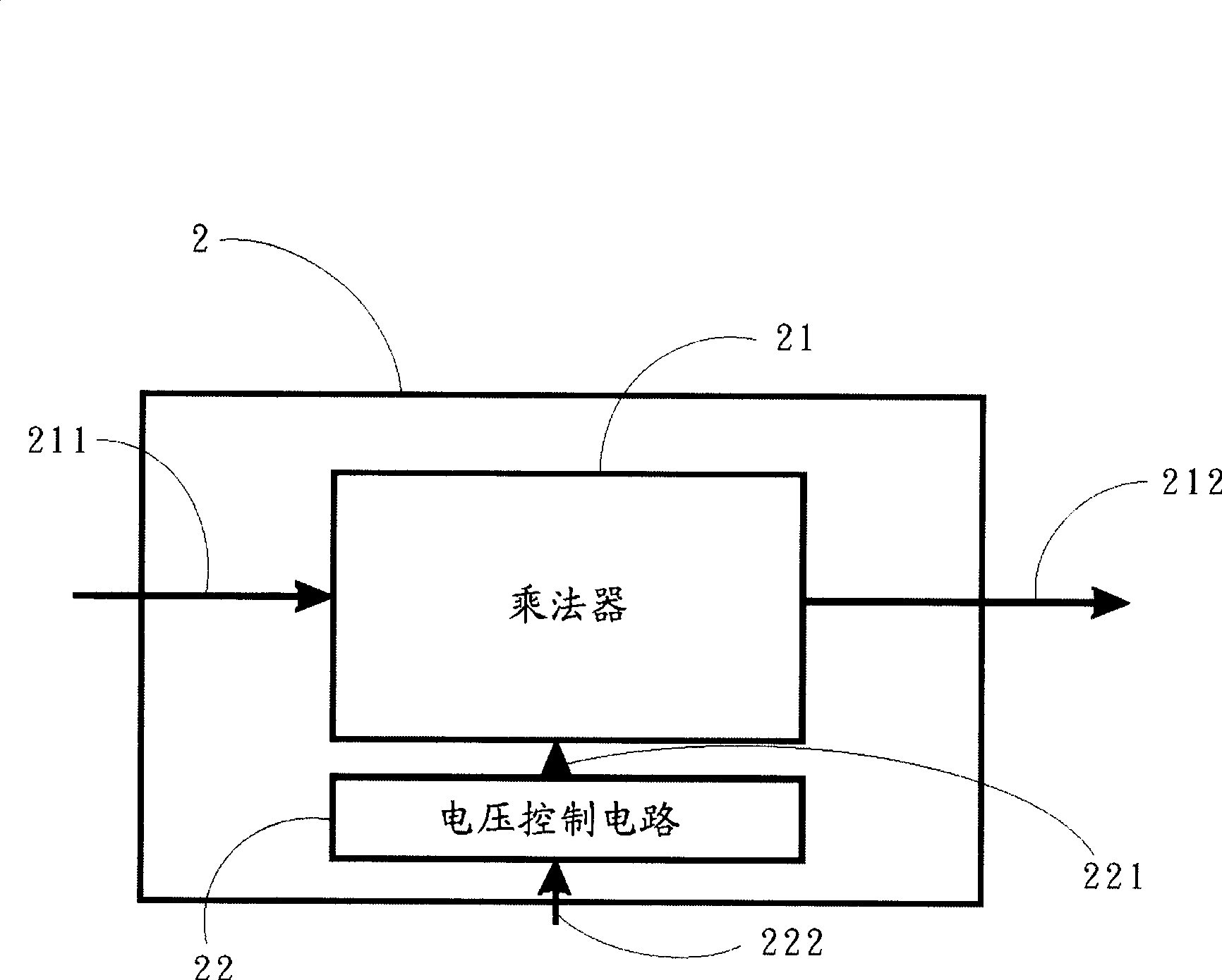
[0031] see figure 2 , figure 2 It is a structural diagram of the variable gain amplifier of the present invention, the variable gain amplifier 2 includes a multiplier 21 and a voltage control circuit 22 coupled to the multiplier 21, the multiplier 21 is used to receive an input signal 211, and according to the control voltage 221 Gain amplifies the input signal 211 to generate an output signal 212 , and the voltage control circuit 22 generates a control voltage 221 according to an input voltage 222 to control the multiplier 21 to amplify the input signal 211 . The multiplier 21 can be a gigabit unit, but not limited thereto.

[0032] see image 3 , image 3 It is a circuit diagram of the voltage control circuit of the present invention, wherein the voltage control circuit 3 includes a control voltage source 31 , a current generating unit 32 , an output voltage generating unit 33 , a reference voltage source 34 and a ground terminal 35 . The control voltage source 31 is c...


PUM


Abstract

The invention provides a voltage control circuit and a variable gain amplifier and particularly relates to a voltage control circuit which comprises a control voltage source used for inputting a single-end control voltage, a current generation unit which is coupled with the control voltage source and a grounding end used for generating a first current according to the single-end control voltage, an output voltage generation unit which is coupled with the current generation unit and used for receiving a reference voltage and generating a first output voltage and a second output voltage according to the first current and the reference voltage, wherein, the first output voltage is higher than the second output voltage. In the voltage control circuit and the variable gain amplifier of the invention, the first output voltage is constantly higher than the second output voltage and a multiplier can complete the gain to an input signal according to the first output voltage and the second output voltage and ensure that the input signal and an output signal have the same polarity.

Description

technical field [0001] The invention relates to a voltage control circuit, especially a voltage control circuit applied to a variable gain amplifier circuit. Background technique [0002] In a variable gain amplifier circuit, a multiplier, especially a Gilbert cell, is usually included to gain the input signal, and a voltage control circuit is also included to control the multiplier to make the input The signal is the same polarity as the output signal. The voltage control circuit in the Gilbert unit usually includes one input terminal and two output terminals, and the gain of the multiplier is controlled by the control voltage generated by the two output terminals. When the variable gain amplifier circuit is in operation, the control voltage generated by one of the output terminals of the voltage control circuit must be always greater than the control voltage generated by the other output terminal, so that the input signal of the multiplier and the output signal have the s...

Claims


Application Information

Patent Timeline
Patent Type & Authority Patents(China)
IPC IPC(8): H03G3/10H03F1/32
Inventor 陈信光谢义滨许哲维
Owner PRINCETON TECH CORP
Learn More