
Method for driving double-gate liquid crystal display panel

A technology of liquid crystal display panel and driving method, which is applied to static indicators, instruments, etc., and can solve the problems of precharging, charging, and charging reverse polarity that are not suitable for double-gate liquid crystal display devices

Active Publication Date: 2012-11-28
CENTURY DISPLAY (SHENZHEN) CO LTD
View PDF0 Cites 0 Cited by
  • Summary
  • Abstract
  • Description
  • Claims
  • Application Information

AI Technical Summary

Problems solved by technology

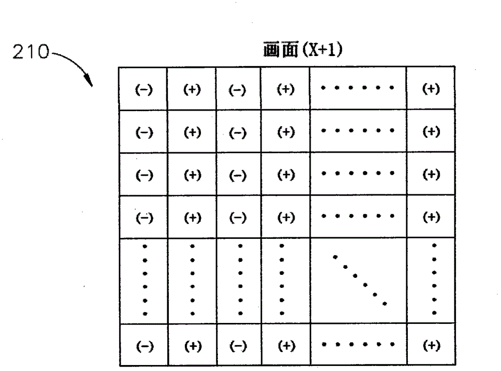
However, since the polarity of the pixel unit PX connected to the first scanning line GL1 is [+-+-+-…], the polarity of the pixel unit PX connected to the second scanning line GL2 is [-+-+-+…] ], the polarity of the pixel unit PX connected to the third scanning line GL3 is [+-+-+-…], so it is impossible to charge the data signal to the pixel unit PX connected to the first scanning line GL1 at the same time. The pixel unit PX in the same column and coupled to the second scanning line GL2 is filled with a pre-charge signal of opposite polarity; similarly, it is also impossible to charge the pixel unit PX connected to the second scanning line GL2 with a data signal while simultaneously charging the same column And the pixel unit PX coupled to the second scanning line GL2 is charged with a pre-charge signal of opposite polarity
[0015] Therefore, the known driving method is not suitable for precharging the single-point plus double-point inversion dual-gate liquid crystal display device.

Method used


Image

  • Method for driving double-gate liquid crystal display panel
  • Method for driving double-gate liquid crystal display panel
  • Method for driving double-gate liquid crystal display panel

Examples


Embodiment Construction

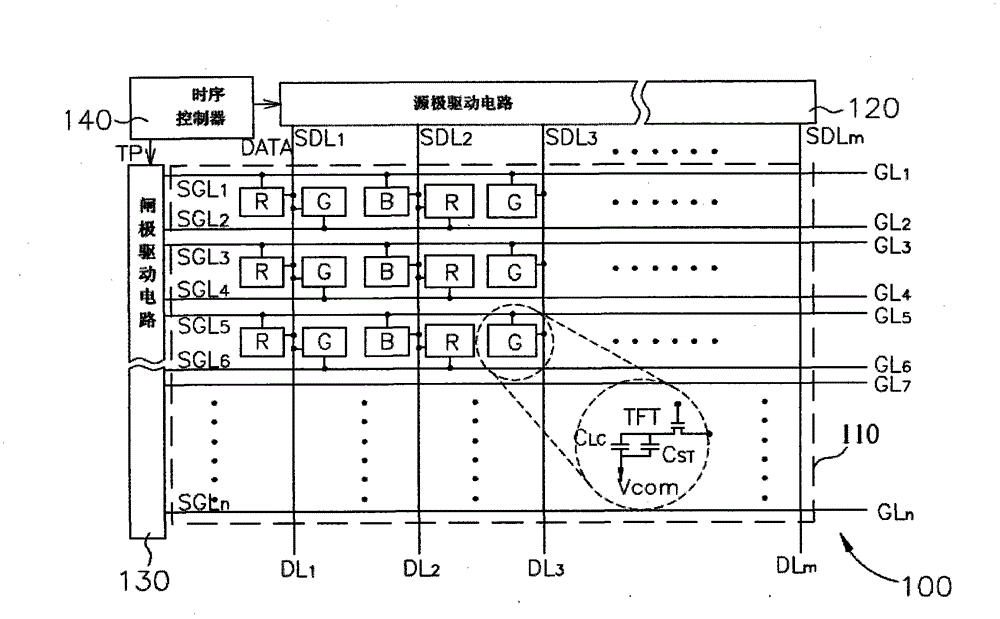
[0033] The driving method of the double-gate liquid crystal display panel of the present invention is based on the structure of the known double-gate liquid crystal display device, and applies the known polarity inversion state of column inversion. Here, the conventional Known structure; so please refer to figure 1 , figure 1 It is a known liquid crystal display device 100 with double gate structure. The dual-gate liquid crystal display device 100 includes a dual-gate liquid crystal display panel 110 , a source driving circuit 120 , a gate driving circuit 130 , and a timing controller 140 . The dual-gate liquid crystal display panel 110 includes a plurality of scanning lines GL arranged in parallel, a plurality of data lines DL perpendicular to the plurality of scanning lines GL, and a plurality of pixel units PX; wherein the plurality of scanning lines GL includes a first The scanning line GL1 , the second scanning line GL2 , . . . , the nth scanning line GLn; the plurality...


PUM


Abstract

The invention discloses a method for driving a double-gate liquid crystal display panel. The method comprises the following steps of: sequentially classifying four scanning lines into one group; at a first period of time, switching on a first scanning line, inputting a first pre-charging signal into a pixel unit connected with the first scanning line, switching on a second scanning line, inputting a first information signal into the pixel unit connected with the first scanning line, inputting a second pre-charging signal into a pixel unit connected with the second scanning line, switching offthe first scanning line and keeping the second scanning line on, inputting a second information signal into the pixel unit connected with the second scanning line and switching off the second scanning line; and at a second period of time, switching on a third scanning line, inputting a third pre-charging signal into a pixel unit connected with the third scanning line, switching on a fourth scanning line, inputting a third information signal into the pixel unit connected with the third scanning line, inputting a fourth pre-charging signal into a pixel unit connected with the fourth scanning line, switching off the third scanning line and keeping the fourth scanning line on, inputting a fourth information signal into the pixel unit connected with the fourth scanning line and switching off the fourth scanning line, wherein the pre-charging signal and the information signal of each pixel unit have the same polarity.

Description

【Technical field】 [0001] The invention relates to liquid crystal display technology, in particular to a method for driving a liquid crystal display panel, which can drive a liquid crystal display (Liquid Crystal Display, LCD) in a pre-charge manner. 【Background technique】 [0002] Liquid crystal display (liquid crystal display, LCD) has the advantages of low radiation, small size and low energy consumption, and has gradually replaced the traditional cathode ray tube (cathode ray tube, CRT) display, and is widely used in notebook computers, Personal digital assistant (personal digital assistant, PDA), flat-screen TV, or information products such as mobile phones. The driving method of liquid crystal display devices generally uses a timing controller to generate various control signals, so that the source driver circuit (source driver) and gate driver circuit (gate driver) can drive the pixel units on the panel accordingly to display the image. According to different driving...

Claims


Application Information

Patent Timeline
Patent Type & Authority Patents(China)
IPC IPC(8): G09G3/36
Inventor 李俊谊
Owner CENTURY DISPLAY (SHENZHEN) CO LTD
Learn More