
Permanent-magnetic electric machine inductance parameter measuring apparatus and method

A technology of inductance parameter and permanent magnet motor, which is applied in the direction of measuring device, motor generator test, measuring electric variable, etc. Effect

Active Publication Date: 2010-09-15
奇瑞新能源汽车股份有限公司
View PDF2 Cites 2 Cited by
  • Summary
  • Abstract
  • Description
  • Claims
  • Application Information

AI Technical Summary

Problems solved by technology

At present, there are no specific test methods for permanent magnet motors in national and international standards, and the permanent magnets in permanent magnet synchronous motors have various shapes and positions, the rotor AC and direct axis magnetic circuits are extremely complex, and the inductance parameters are not only related to the saturation of the magnetic circuit. Related, there is also a cross saturation phenomenon between the orthogonal and direct axis magnetic circuits, which is more complicated to measure
At present, the finite element analysis method can be used to determine the inductance parameters. However, if the magnetic saturation is obvious, the finite element analysis method can be applied, but it needs to analyze the distribution of multiple currents in the winding, which requires a lot of computing resources, which is relatively complicated and cumbersome.
The commonly used DC attenuation method and voltage integration method have relatively high requirements for test equipment and are relatively complicated.

Method used


Image

  • Permanent-magnetic electric machine inductance parameter measuring apparatus and method
  • Permanent-magnetic electric machine inductance parameter measuring apparatus and method
  • Permanent-magnetic electric machine inductance parameter measuring apparatus and method

Examples


Embodiment approach 1

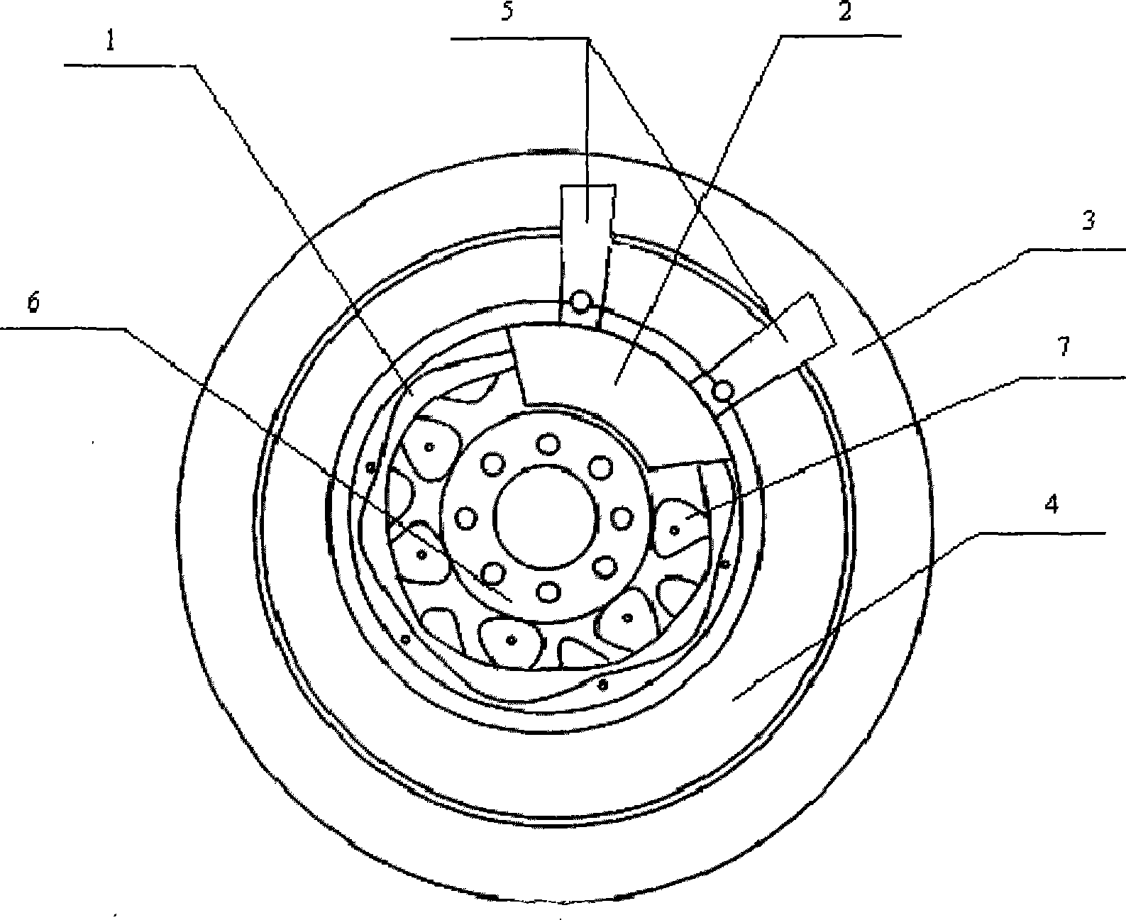
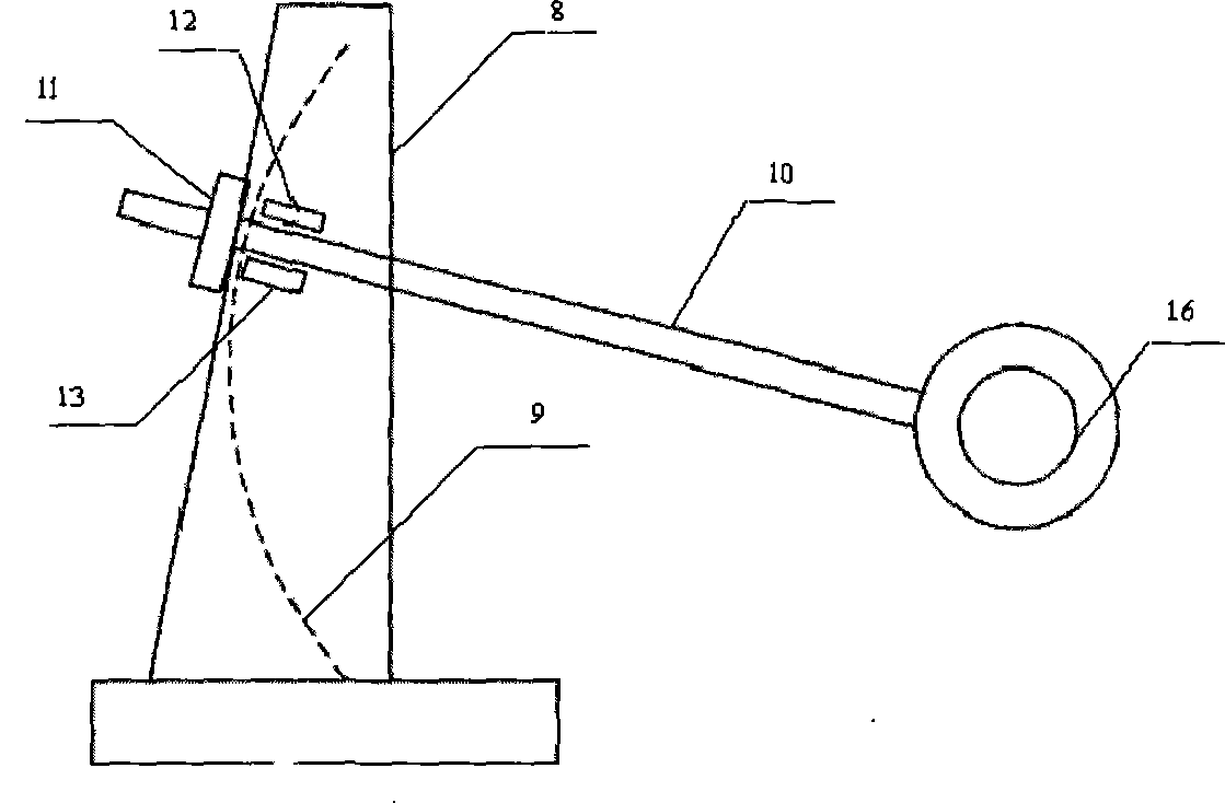
[0020] In this method, the B and C phases of the stator are first short-circuited, and then the rotor magnetic pole is fixed at the position where the angle between the magnetic pole d axis and the A phase is 0 degrees through the rotor position monitoring device and the rotation fixing device, and then applied to the stator AB phase. The voltage pulse signal records the information of the total current i flowing through the series circuit, that is, the current flowing through phase A, the voltage u information at both ends of the series circuit and the sampling time t information.

[0021] When the rotor magnetic pole is fixed at the position where the angle between the magnetic pole d-axis and phase A is 0 degrees, the direct-axis inductance of the stator winding at time t is calculated according to the following formula:

[0022] ψ d ( t ) = ψ d ( ...

Embodiment approach 2

[0029] The difference between this embodiment and Embodiment 1 is that the A phase of the stator is replaced by the B phase, that is, the A and C phases of the stator are short-circuited, and the voltage pulse signal is applied to the AB phase of the stator, and the measurement is the current flowing through the B phase and The voltage of BC phase, the u in the formula will be used in the final calculation ab (t) with u bc (t) instead, i a (t) with i b (t) Instead.

Embodiment approach 3

[0031] The difference between this embodiment and Embodiment 1 is that phase A of the stator is replaced by phase C, that is, the two phases A and B of the stator are short-circuited, and a voltage pulse signal is applied to the phase CB of the stator, and the current and phase C flowing through the phase C are measured. The voltage of CB phase, the u in the formula will be used in the final calculation ab (t) with u cb (t) instead, i a (t) with i c (t) Instead.


PUM


Abstract

The invention discloses a simple testing method for testing the inductance of a direct axis and a quadrature axis of a permasyn motor, which has the following procedures that: any two phases of a stator are short-circuited, then a magnetic pole of a rotator is fixed in the position of an included angle of 0 degree or 90 degrees between the d axis of the magnetic pole and the phase of the stator which is not short-circuited by a simple rotator position adjusting mechanism; a voltage pulse signal is imposed on a series circuit which is formed by the non-short circuited phase of the stator and any other phase, the information of the whole current i which flows through the series circuit, the information of the voltage u at the two ends of the series circuit and the information of sampling time t are recorded, then the direct axis inductance and the quadrature axis inductance of the stator winding at the time t can be obtained after simple calculations. The simple testing method for testing the inductance of a direct axis and a quadrature axis of a permasyn motor also discloses a simple testing device for testing testing inductance of a direct axis and a quadrature axis of a permasyn motor. By using the techniques of the simple testing method for testing the inductance of a direct axis and a quadrature axis of a permasyn motor, a precise test of the inductance of a direct axis anda quadrature axis of a permasyn motor can be realized, and the calculation is simple, without occupying a great amount of calculating resources.

Description

technical field [0001] The invention belongs to the field of automatic control, in particular to a motor control system. Background technique [0002] The direct-axis and quadrature-axis inductances of permanent magnet synchronous motors have a great influence on the steady-state and dynamic performance of permanent magnet synchronous motors. The accuracy of direct-axis and quadrature-axis inductance parameters is not only important for predicting torque and field weakening performance, but also for design Control system design such as maximum efficiency and power factor is very critical, so how to determine the direct axis and quadrature axis inductance parameters is very important. Since permanent magnet synchronous motors are excited by permanent magnets, the test methods for their alternating and direct axis inductance parameters are quite different from those of electric excitation synchronous motors, and their test content and testing techniques have their own particul...

Claims


Application Information

Patent Timeline
Patent Type & Authority Patents(China)
IPC IPC(8): G01R27/26G01R31/34
CPCG01R31/34
Inventor 罗晓
Owner 奇瑞新能源汽车股份有限公司
Learn More