
Petrol engine intake duct

A gasoline engine, intake port technology, applied in engine components, machines/engines, cylinders, etc., can solve problems such as unreachable, and achieve the effect of reducing flow resistance

Inactive Publication Date: 2008-09-10
CHERY AUTOMOBILE CO LTD
View PDF0 Cites 10 Cited by
  • Summary
  • Abstract
  • Description
  • Claims
  • Application Information

AI Technical Summary

Problems solved by technology

Therefore, the intake ports of general gasoline engines cannot meet the high tumble ratio requirements of in-cylinder direct injection gasoline engines.

Method used


Image

  • Petrol engine intake duct
  • Petrol engine intake duct
  • Petrol engine intake duct

Examples


Embodiment Construction

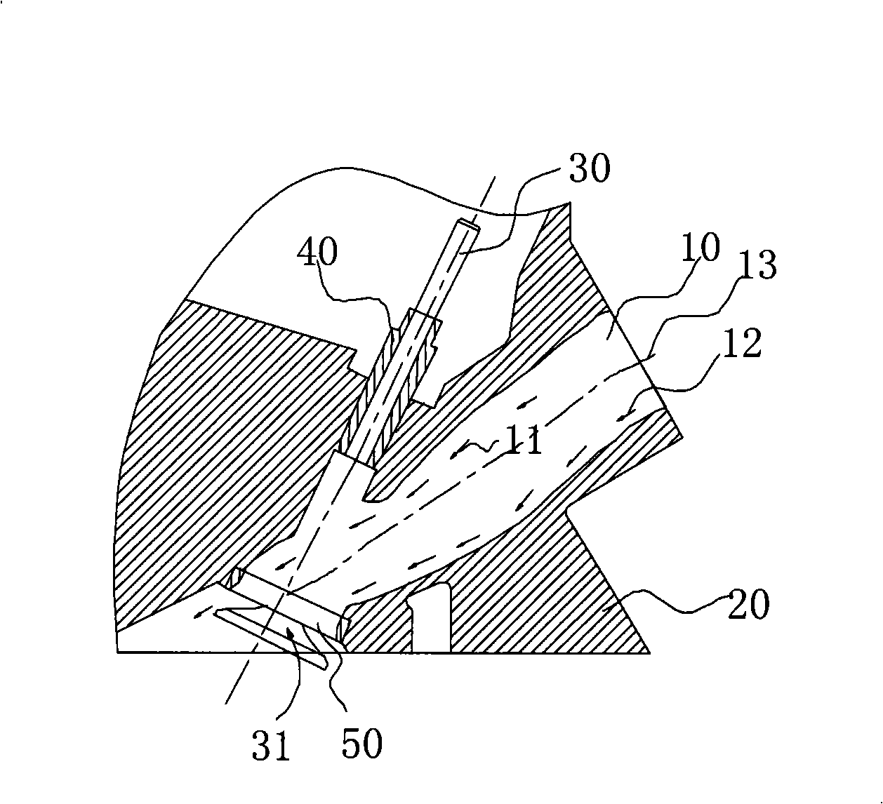
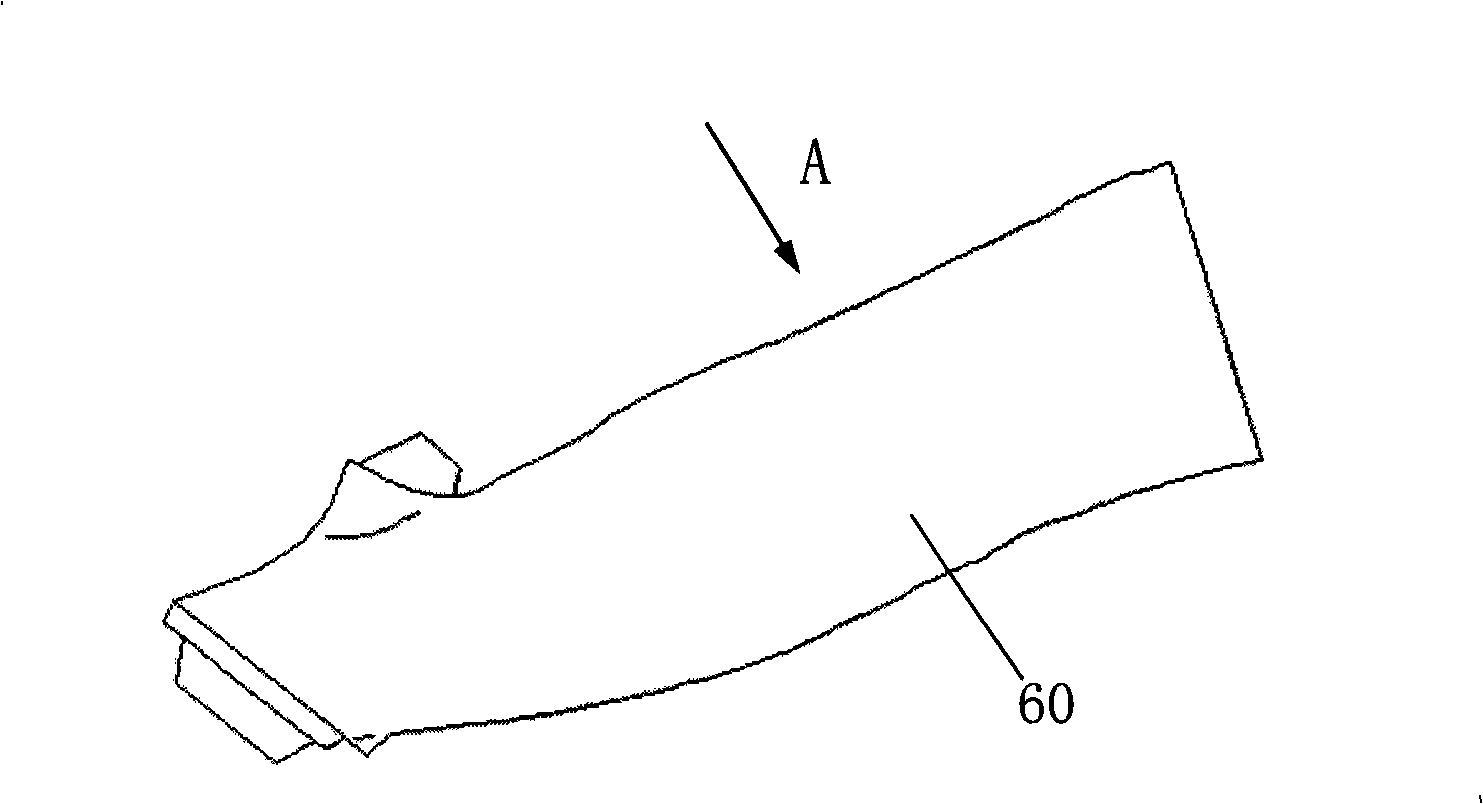
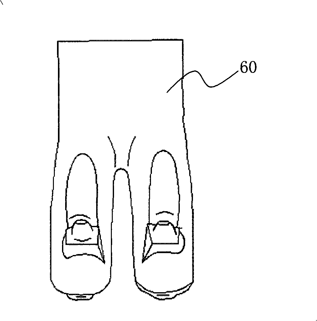
[0012] Such as figure 1 As shown, the intake port 10 on the gasoline engine cylinder head 20 is straight and extends obliquely to the valve. The valve 30 is arranged to move in the valve guide 40 . The apertures of the inlet section of the air inlet passage 10 are approximately the same, and the air outlet section is closed in a gentle shape. The included angle between the centerline of the air inlet passage 10 and the centerline of the valve stem provided above is 8~ 45°, the preferred included angle is 8-30°, the best included angle is 8-15°, and the angle of the embodiment given in the accompanying drawings is 12°. The setting of the above-mentioned angles actually needs to match the angle and radian of the valve stem’s cone surface. A small angle can ensure a compact arrangement of the air passage and the cylinder head, which can effectively reduce the overall weight of the engine and save layout space.

[0013] exist figure 1 , 4 , 5, it can be seen that the upper airf...


PUM


Abstract

The invention relates to a novel inlet channel of a gasoline engine, and the flat inlet channel is extended to a valve in the oblique direction. Because of the inlet channel has a flat shape, under the circumstance that flow coefficient is larger, airflow receives smaller flow resistance in the inlet channel. The shape of the inlet channel provided reduces the flow resistance, and the flow coefficient of the inlet channel can meet the requirement of an in-cylinder direct-injection engine.

Description

technical field [0001] The invention relates to a new type of intake port of a gasoline engine, which is especially suitable for an engine with direct injection and homogeneous combustion in a cylinder. Background technique [0002] In-cylinder direct injection has become one of the trends in the development of gasoline engines. In-cylinder direct injection gasoline engines are divided into homogeneous combustion and stratified combustion according to the formation of the mixture in the cylinder. Homogeneous combustion requires the gas entering the cylinder through the air passage to generate a high tumble flow ratio, which is conducive to the formation of a homogeneous mixture. At present, most of the airway designs are suitable for the airway of the gasoline engine injected by the intake manifold, and only put forward higher requirements on the flow coefficient of the airway in order to achieve a large intake air volume; while the tumble flow formed in the cylinder lower...

Claims


Application Information

Patent Timeline
IPC IPC(8): F02F1/42
Inventor 魏建城黄建国
Owner CHERY AUTOMOBILE CO LTD
Learn More