
Optical scanning device and image forming apparatus

An optical scanning device and scanning line technology, which are applied in the electrical recording process using charge patterns, equipment and optics, etc., can solve problems such as inability to form images, increase the degree of freedom, and reduce the number of parts. The effect of the number of

Inactive Publication Date: 2008-09-03
RICOH KK
View PDF2 Cites 6 Cited by
  • Summary
  • Abstract
  • Description
  • Claims
  • Application Information

AI Technical Summary

Problems solved by technology

When the scanning line is bent or inclined, the correct latent image corresponding to the image information cannot be formed on the surface of the latent image carrier, and a normal image cannot be formed

Method used


Image

  • Optical scanning device and image forming apparatus
  • Optical scanning device and image forming apparatus
  • Optical scanning device and image forming apparatus

Examples


Embodiment Construction

[0033] Hereinafter, one embodiment of the present invention applied to a printer as an image forming apparatus will be described. Although this embodiment has been described by taking a tandem image forming apparatus of an intermediate transfer method as an example, it is not limited thereto.

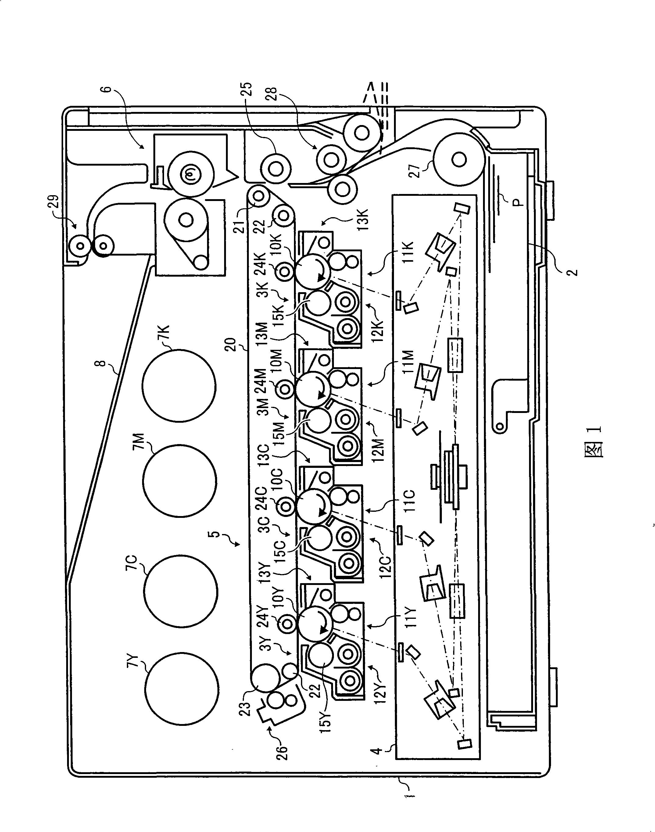
[0034] FIG. 1 is a schematic configuration diagram of a printer according to the present invention.

[0035] The printer includes a device body 1 and a paper feeding cassette 2 that can be pulled out from the device body 1 . In the central part of the apparatus body 1, image forming stations 3Y, 3C for forming toner images (visible images) of respective colors such as yellow (Y), cyan (C), magenta (M), and black (K) are provided. , 3M, 3K. Hereinafter, components for yellow, cyan, magenta, and black are indicated by adding letters Y, C, M, and K to each symbol.

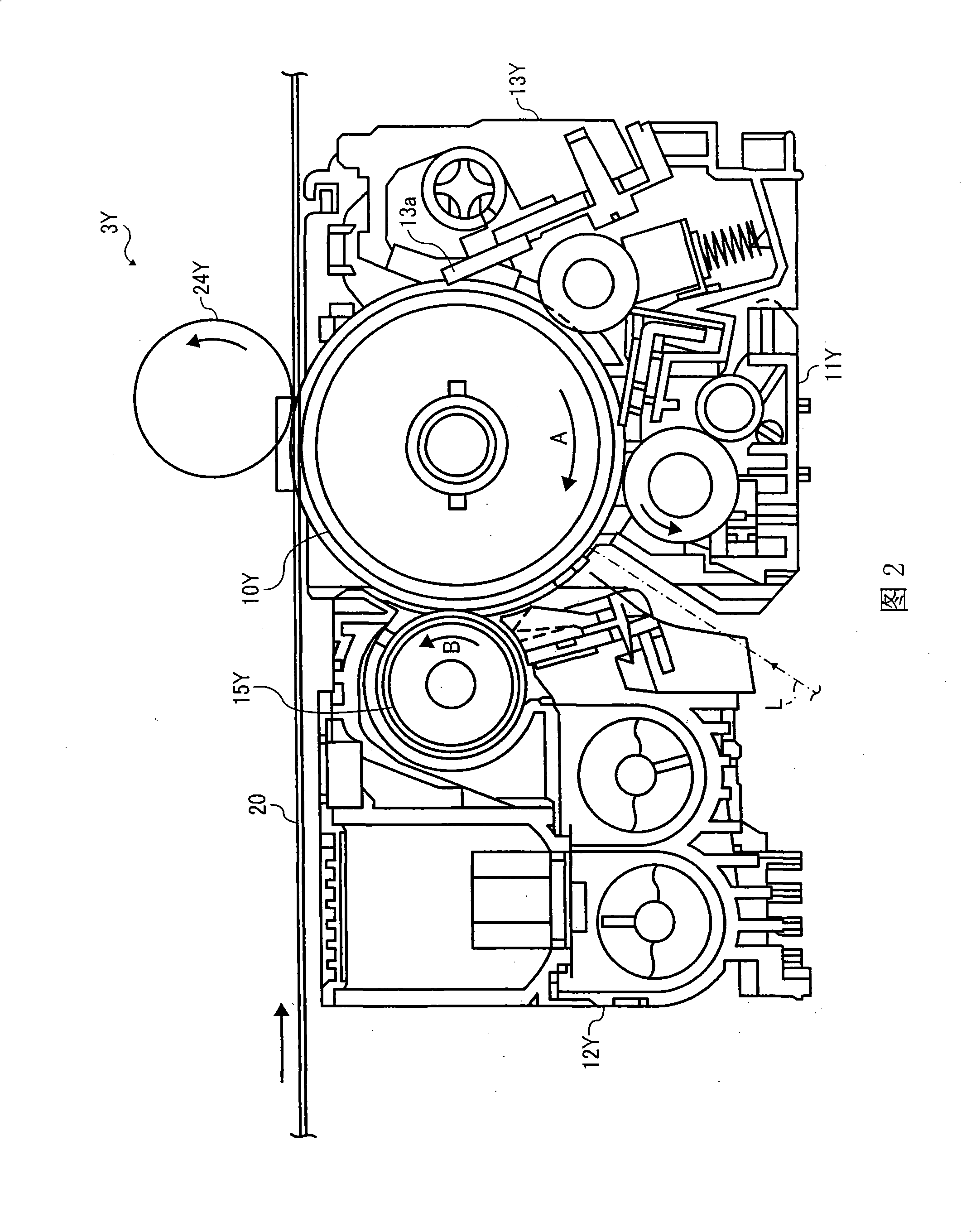
[0036] Figure 2 is a schematic configuration diagram of an imaging station in yellow (Y). Note that other imaging station...


PUM


Abstract

The invention provides an optical scanning device and an image forming device, wherein a light beam emission unit is configured to emit a light beam, a main scanning line deflection unit configured to deflect the light beam in a main scanning direction to emit a scanning beam, a scanning lens configured to focus the scanning beam in the main scanning direction and a sub-scanning direction, a reflective optical element configured to deflect the scanning beam, a tilt adjustment unit configured to change a position of the reflective optical element to adjust a tilt of a scanning line of the scanning beam irradiating a target to be irradiated, and a curve adjustment unit configured to bend the reflective optical element to adjust a curve in the scanning line of the scanning beam irradiating the target to be irradiated.

Description

technical field [0001] The present invention relates to an optical scanning device and an image forming device. Background technique [0002] In image forming apparatuses such as copiers, printers, and facsimile machines, it is known to irradiate writing light based on image information onto a latent image carrier, and to form a latent image on the latent image carrier by scanning therefor, and An image is obtained by developing the latent image. An optical writing device (optical scanning device) that irradiates writing light and scans it generally includes a light source, a polygon mirror with a deflector, an fθ lens, a long lens, and a mirror for reflecting optical elements. [0003] The writing light emitted by the light source is deflected and scanned at a uniform angular velocity by the rotating polygon mirror. The writing light deflected and scanned at a uniform angular velocity enters the fθ lens, is condensed in the direction of the main scanning line, and is corr...

Claims


Application Information

Patent Timeline
Patent Type & Authority Applications(China)
IPC IPC(8): G02B26/10G03G15/01G03G15/00B41J2/47
CPCG02B26/0825G02B26/123G02B26/126
Inventor 庄司胜则
Owner RICOH KK
Learn More