Magnetic driven metering pump

A metering pump and magnetic drive technology, which is applied in the direction of pumps, pump control, pump components, etc., can solve the problems of metering volume drop, working pressure rise, error aggravation, etc., and achieve the effect of improving metering accuracy and reducing dependence

Active Publication Date: 2008-08-20
PROMINENT
View PDF0 Cites 9 Cited by
  • Summary
  • Abstract
  • Description
  • Claims
  • Application Information

AI Technical Summary

Problems solved by technology

The amount of deflection reduces the effective stroke movement and leads to an increase in operating pressure and a decrease in metering volume
In normal use, this characteristic degradation is more significant than the range allowed by the metering accuracy
As a result, magnetically driven metering pumps generally cannot be used over a wide range of operating pressures with the required accuracy, moreover, errors caused by calibration are exacerbated by being used in further calculations
However, the calibration measurements described must be carried out for use under real operating conditions, especially when aggressive chemicals are used, which is a very difficult step
[0008] The existing magnetic drive metering pump has only some simple parts and is easy to manufacture, but it has relatively limited application, and at the same time, it will be affected by the unfavorable factors of the hydraulic characteristics in the metering process compared with the motor drive pump
Motor driven, e.g. via gears or cams, can be used in more ways and has better metering characteristics in many processes, but is also more expensive to produce

Method used


Image

  • Magnetic driven metering pump
  • Magnetic driven metering pump
  • Magnetic driven metering pump

Examples


Embodiment Construction

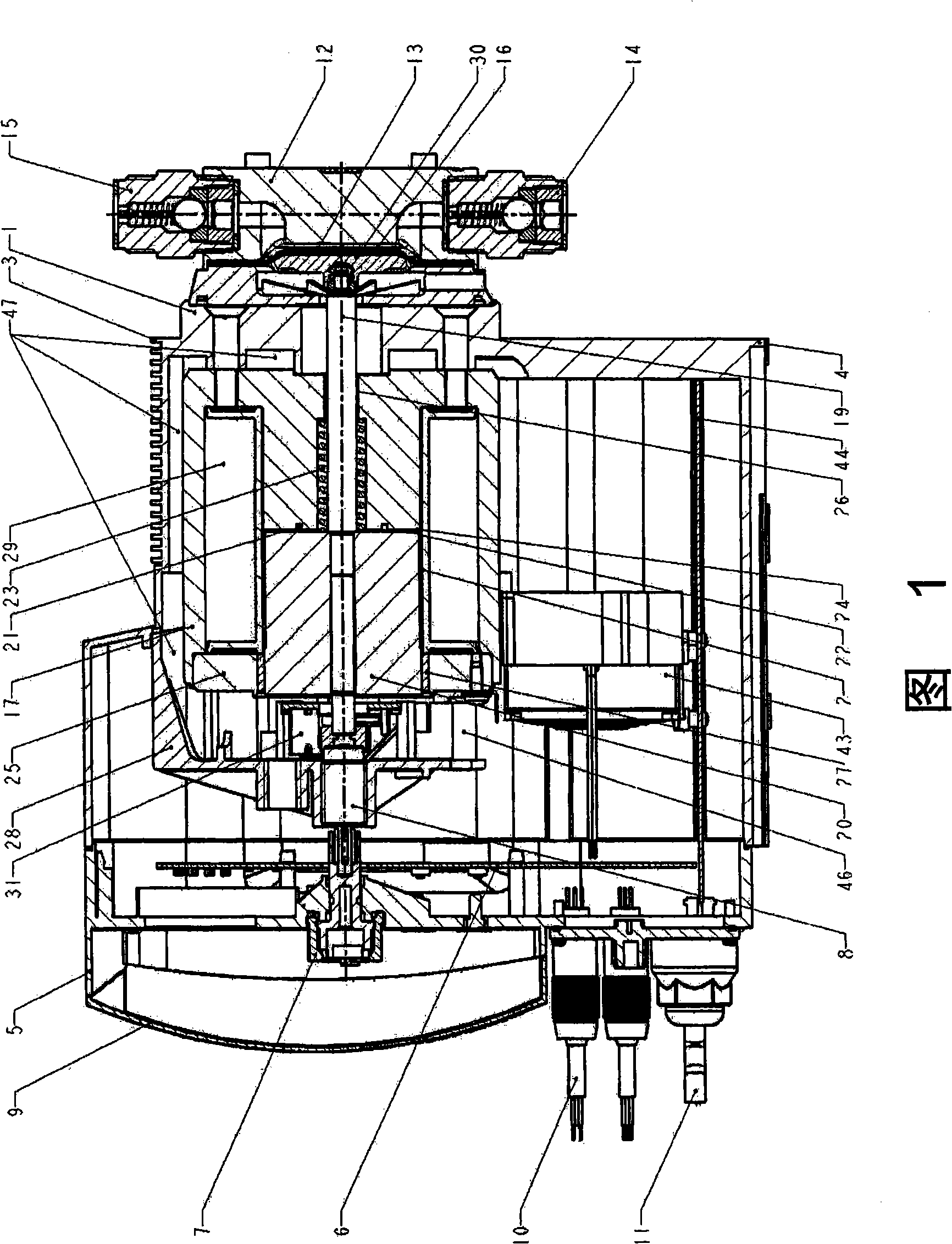
[0064]Figure 1 shows a longitudinal section of a magnetically driven metering pump (MD). On the lower side is the housing 1 of the bottom plate 4 with ribs 3 close to the magnets (upper part) to prevent hot surfaces from being touched. As is known, the upper region of the housing 1 contains a magnetically actuated cover plate 17 . One side of the casing is closed by a casing cover 5 installed and fixed on the casing. At the center of the housing cover 5 and coaxially with the longitudinal axis 18 of the substantially rotationally symmetrical magnet, a manually adjustable correction member 7 is incorporated into the housing cover for adjustment to limit the axial movement and Stroke correction pin 8 for diaphragm pump stroke. The correction part 7 and other operating elements are protected by a cover 9 . Below the cover 9 is an interface for a control line 10 or a mains line 11 . On the side opposite the housing is a metering head 12 , in which a membrane 13 , for example m...


PUM


Abstract

The invention provides a magnetic driving metering pump. A movable pushing part which is fixed on a connecting rod can axially move on a longitudinal shaft in a magnetic cover plate which is fixedly anchored in a pump shell; therefore, after a magnetized coil is driven (started) by getting electricity, the pushing part and the connecting rod overcome the force of a recovery spring and are then pulled into the magnetic cover plate and enter one hole in the magnetic cover plate by reducing the clearance; the pushing part returns to an original position by the recovery spring after the magnet is stopped; therefore, under the continuous starting and stopping of the magnetized coil, the pushing part and an elastic displacement part are driven to carry out vibration; wherein, a diaphragm is alternatively matched with an outlet valve and an inlet valve; a pumping stroke (pressure stroke) and an injection stroke are generated in a metering head which is arranged along the direction of the longitudinal axis. In the magnetic driving metering pump, a benchmark part is connected with a module which consists of the pushing part and the connecting rod; the position of the benchmark part is detected by a position sensor; wherein, the position sensor provides a practical signal which has a fixed relation with the position of the benchmark part; furthermore, the motion precision of the unit which consists of the pushing part and the connecting rod is controlled by a control circuit so as to meet a prearranged nominal drawing.

Description

technical field [0001] The invention relates to a magnetically driven metering pump according to the preamble of claim 1 . Background technique [0002] Magnetically driven metering pumps of that type are generally known and are adapted to the various requirements by means of extended loading. They are used for metering volumes, where metering takes place by conveying a closed volume. The metered volume per stroke corresponds to the volume difference caused by the movement of the diaphragm. [0003] In this magnetically driven metering pump, a movable pushing part is mounted on a fixed magnetic cover, so that when the magnetizing coil is driven, it can be inserted into the magnetic cover, so that the gap is narrowed and after power off, the push The part will be pushed back to the original position by the return spring. The connecting rod is fixedly connected to the pusher and transmits this movement and force to the flowmeter diaphragm. [0004] In the simplest example,...

Claims


Application Information

Patent Timeline
Patent Type & Authority Applications(China)
IPC IPC(8): F04B43/04F04B13/00F04B49/06F04B53/08
Inventor T·弗雷登伯格D·A·霍勒
Owner PROMINENT
Why Eureka
Try Eureka