
Thin film -type adjustable phase retarder

A technology of phase retarder and phase retarder, applied in instruments, polarizing elements, installation, etc., can solve the problems of difficult quantitative control of phase difference, high price, inappropriate use of large-diameter beams, etc., and achieves a high anti-laser damage threshold. , Simple structure, easy to make effect

Inactive Publication Date: 2008-08-06
SHANGHAI INST OF OPTICS & FINE MECHANICS CHINESE ACAD OF SCI
View PDF0 Cites 6 Cited by
  • Summary
  • Abstract
  • Description
  • Claims
  • Application Information

AI Technical Summary

Problems solved by technology

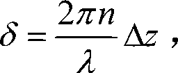
However, the phase difference is a fast-changing parameter in time or space. For example, after two beams of light are transmitted through the spatial distance difference ΔZ, the phase difference generated is: δ = 2 πn λ Δz , Where λ is the wavelength, and n is the refractive index of the propagation medium. When ΔZ changes a wavelength, the phase difference changes by 2π radians, so the quantitative control of the phase difference is not easy
A commonly used phase compensator is the Babinet-Solier phase compensator, but this phase retarder is made of crystal, but it is not suitable for large aperture beams, and the price is more expensive

Method used


Image

  • Thin film -type adjustable phase retarder
  • Thin film -type adjustable phase retarder
  • Thin film -type adjustable phase retarder

Examples


Embodiment Construction

[0024] The present invention will be further described below in conjunction with the embodiments and accompanying drawings, but the protection scope of the present invention should not be limited thereby.

[0025] Please refer to FIG. 1 first. FIG. 1 is a schematic diagram of the overall structure of the film-type adjustable phase retarder of the present invention. It can be seen from the figure that the film-type adjustable phase retarder of the present invention consists of a first phase retarder 7 and a second phase retarder 8 , the first optical alignment frame 4, the second optical alignment frame 5 and a rotating platform, and its positional relationship is: the rotating platform is composed of a fixed base plate 1 and a rotating platform 2, and the first phase retarder 7 and the second phase retardation plate 8 are respectively pasted in the mirror frames of the first optical adjustment frame 4 and the second optical adjustment frame 5, and the first optical adjustment f...


PUM


Abstract

The invention provides a thin-film type adjustable phase retarder which consists of two thin-film type phase delay plates, two three-dimensional optical adjusting mounts and a precise rotating platform. Two phase delay plates are arranged on the rotating platform and ensure that reflecting surfaces are parallel; a beam of light enters to the first phase delay plate at a certain angle, reflects to the second phase delay plate and emerges parallel to the incident light direction through the second reflection. The rotating platform rotates to change an incidence angle of the beam of light; the phase delay or compensation dosage is also changed along the change of the incident angle, thereby realizing precise and tunable phase delay. The thin-film type adjustable phase retarder is characterized in simple structure, easy manufacturing, high degree of precision, simple operation, multi-purpose, etc.

Description

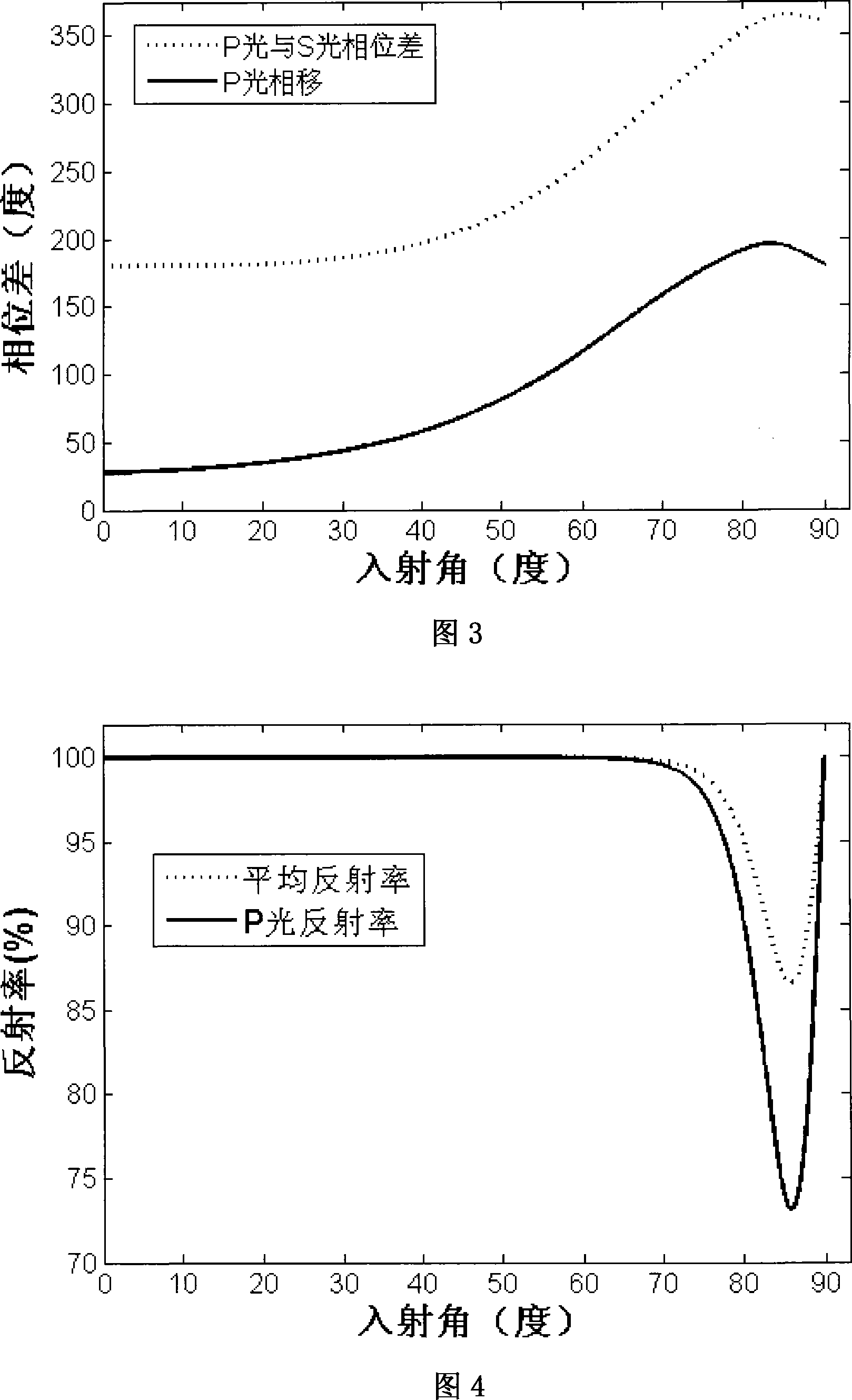
technical field [0001] The present invention is related to thin films, and is a thin film adjustable phase retarder. It uses a special phase retardation film to adjust or compensate the phase with high precision. It can be applied to the optical path of phase control or compensation, and is simple and practical. technical background [0002] Phase is an important parameter to describe the intrinsic characteristics of beams, and it is also a function of time and space. More often used is the phase difference, which is the difference in phase between two different beams. In the interference of light, the phase difference plays an important role. If the phase difference can be precisely controlled, the desired interference result can be obtained; in the polarization of light, the phase difference is even more important, such as changing the two vibration directions of the beam The phase difference can realize the conversion between elliptically polarized light and linearly pol...

Claims


Application Information

Patent Timeline
Patent Type & Authority Applications(China)
IPC IPC(8): G02B27/28G02B7/00G02B5/30
Inventor 董洪成李笑申雁鸣黄建兵易葵邵建达范正修
Owner SHANGHAI INST OF OPTICS & FINE MECHANICS CHINESE ACAD OF SCI
Learn More