Switch device

A technology for switching devices and switching devices, which is applied to electrical switches, electrical components, circuits, etc., can solve the problems of easy reliability decline, weakened elastic force, and deformation of the casing.

Active Publication Date: 2008-07-30
ALPS ALPINE CO LTD
View PDF1 Cites 0 Cited by
  • Summary
  • Abstract
  • Description
  • Claims
  • Application Information

AI Technical Summary

Problems solved by technology

Due to the heating applied to the assembled body during the brazing, in the above-mentioned prior art, the elastic force of the elastic movable contact may be weakened due to heat, resulting in a decrease in the elastic force of the movable contact. , it is difficult to ensure the required contact pressure
In addition, heating the above-mentioned assembly in a state where the elastic force of the movable contact is applied to the case via the fixed contact may cause deformation on the case.
In this way, in the prior art, there is also a problem that the reliability of the switch device is easily reduced when the switch device is mounted on the circuit board by soldering.

Method used


Image

  • Switch device
  • Switch device
  • Switch device

Examples


no. 8 Embodiment approach

[0119] [Structure of the eighth embodiment]

[0120] Fig. 21 is a side view showing main parts of an eighth embodiment of the present invention. In this eighth embodiment, as in the first embodiment, an operating body is constituted by a driving member 45 and a holding member 46 holding a movable contact 47 . In addition, as in the seventh embodiment, an inclined surface 45b is formed on the pressing portion 45a forming the contact portion of the driving member 45, and an inclined surface with the driving member 45 is formed on the pressed portion 46a forming the contact portion of the holding member 46. 45b opposite to the inclined surface 46b. In addition, on the inclined surface 46 b of the holding member 46 , a hemispherical convex portion 46 c that engages with the inclined surface 45 b of the drive member 45 is formed. The inclined surface 45b of the driving member 45 and the inclined surface 46b of the holding member 46 are each similar to the first embodiment, and ar...

no. 9 Embodiment approach

[0123] [Structure of the ninth embodiment]

[0124] Fig. 22 is a side view showing main parts of a ninth embodiment of the present invention. In this ninth embodiment, similarly to the fourth embodiment, the cover member 49 covering the storage portion 48a of the not-shown case has a curved surface that protrudes toward the second fixed contact side disposed in the not-shown case. The protrusion 49 a and the operating body 50 that slides the movable contact 51 are formed of a member having an inclined surface 50 a that can come into contact with the protrusion 49 a of the cover member 49 . The inclined surface 50 a of the operating body 50 is formed in a shape that gradually approaches the coil spring 53 as it approaches the inner bottom surface of the housing portion 48 a (not shown). The movable contact 51 is entirely made of a conductive metal body, and is installed on the operating body 50 made of, for example, synthetic resin by insert molding, and a second fixed contact...


PUM


Abstract

In a voltage generating circuit for a semiconductor memory device, each of a plurality of reset signal generators individually generates a reset signal in response to one of a plurality of external source voltages. The plurality of external source voltages have different voltage levels. An output voltage generator generates a plurality of output voltages by independently driving each of the plurality of external source voltages in response to a corresponding one of the plurality of reset signals. The output voltage generator outputs the plurality of output voltages through a common output terminal.

Description

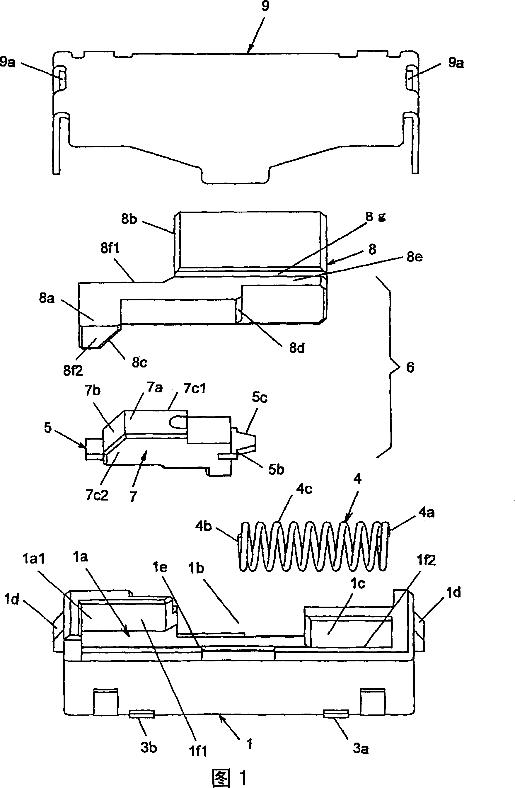
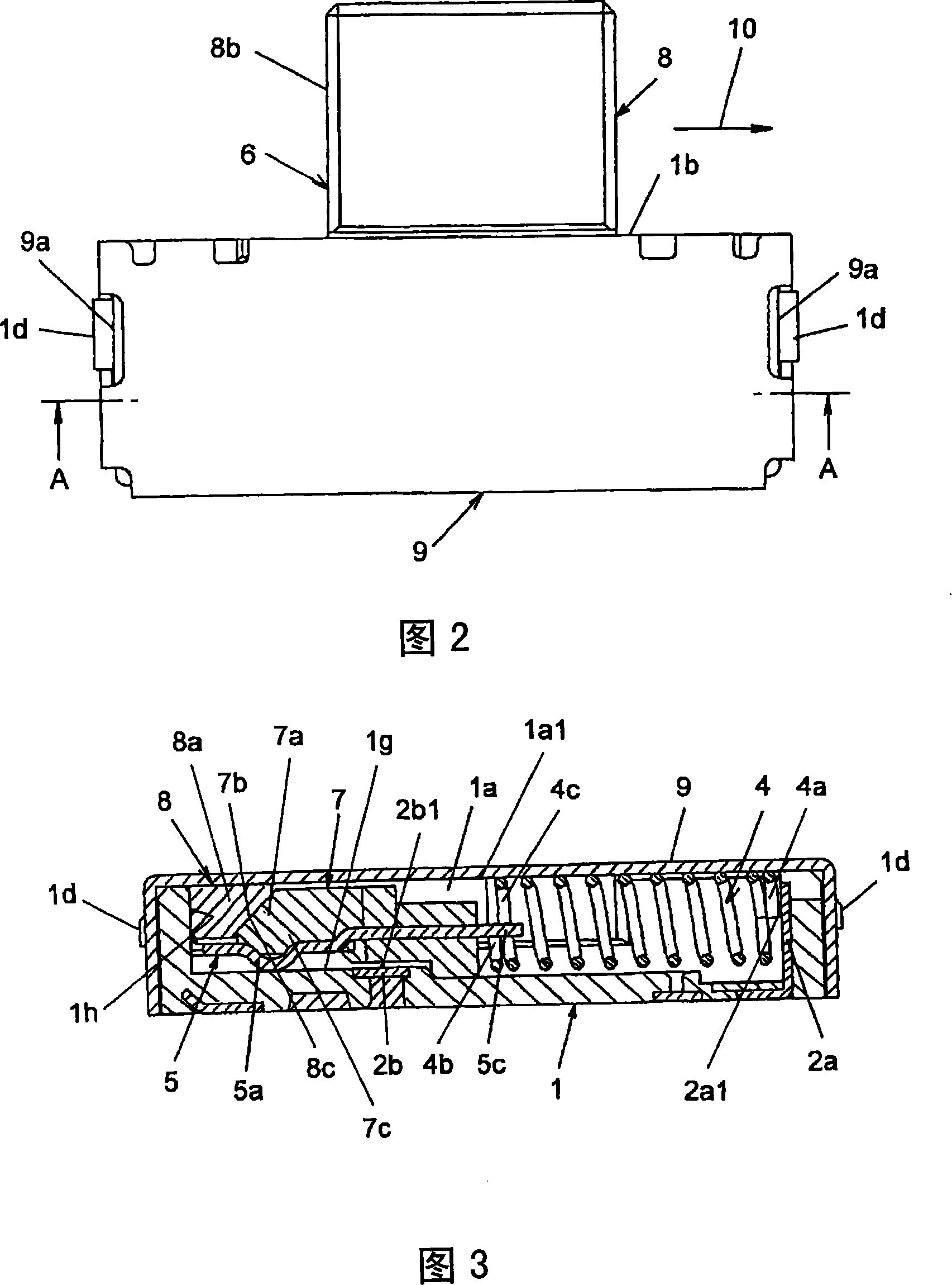
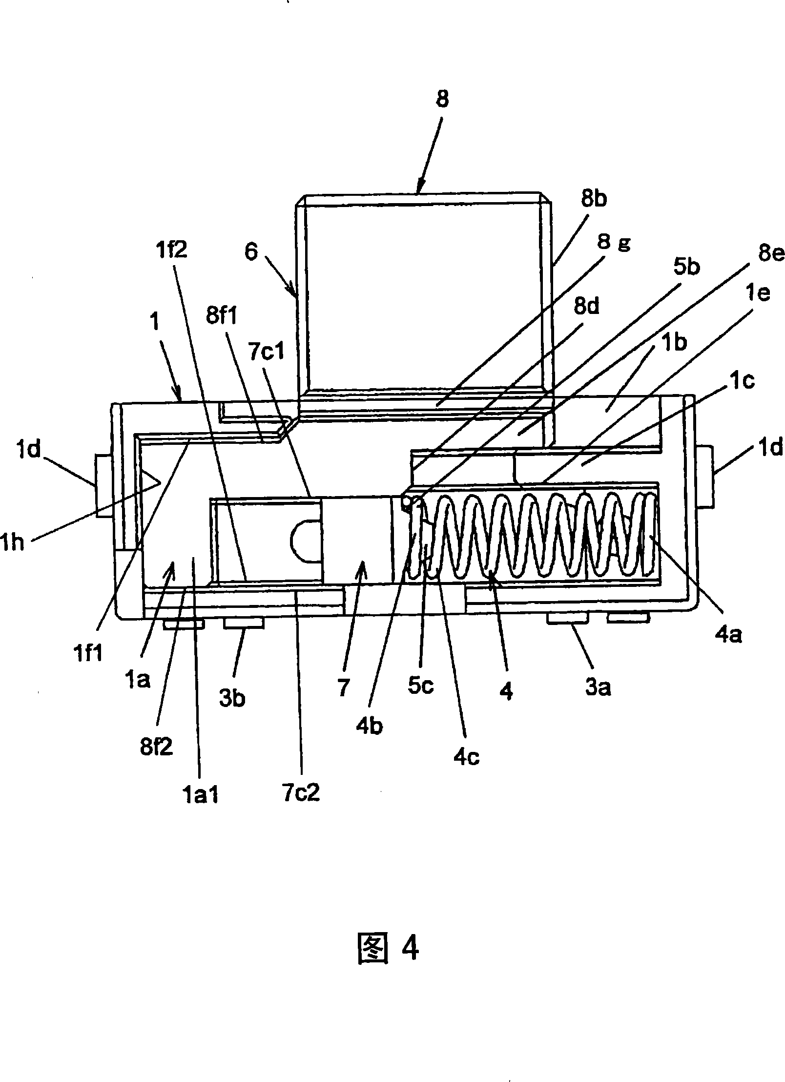
technical field [0001] The present invention relates to a switch device effectively used for a key lock of a mobile phone or the like. Background technique [0002] As such prior art, there is a technique described in Patent Document 1. This patent document 1 discloses a self-resetting slide switch, that is, a switch device, which includes: a frame composed of a case and a cover member covering the case; In the storage part of the body, the elastic movable piece that can contact the fixed contact is the elastic movable contact; and the sliding body that holds the movable contact and can slide in one direction is the operating body. The accommodating part of the contact has an opening at the top and is made of synthetic resin. In addition, an elastic member that is a coil spring that is arranged in the housing portion of the housing to return the operating body to its initial position is provided, and the operating body is slid against the elastic force of the elastic membe...

Claims


Application Information

Patent Timeline
Patent Type & Authority Applications(China)
IPC IPC(8): H01H15/02H01H15/10
CPCH01H13/26H01H13/48H01H15/02H01H15/102
Inventor 小原启志冈西纪昌佐佐木基成
Owner ALPS ALPINE CO LTD
Why Eureka
Try Eureka