
Solid imaging apparatus and method

A kind of equipment and imaging technology, applied in the field of solid imaging equipment, can solve problems such as too many moving parts and complex systems, increasing costs, and contamination of cured resin blocks

Active Publication Date: 2008-07-30
3D SYST INC
View PDF3 Cites 14 Cited by
  • Summary
  • Abstract
  • Description
  • Claims
  • Application Information

AI Technical Summary

Problems solved by technology

[0004] Despite the development of various devices and methods for solid imaging, there are still many shortcomings to be addressed
The devices and methods used to perform solid imaging tend to be somewhat characterized by excessive moving parts and complex systems which can require considerable effort to care, maintain and operate
Laser imaging and UV imaging systems tend to be costly, making these systems impractical for many applications
Complicated and tedious alignment steps to align radiation source and image plane reduce efficiency and increase cost
Large volumes of liquid resin used in stereolithography are expensive and can be contaminated with cured resin clumps

Method used


Image

  • Solid imaging apparatus and method
  • Solid imaging apparatus and method
  • Solid imaging apparatus and method

Examples


Embodiment Construction

[0093] The present invention is best understood by reference to the specific embodiments shown in the drawings and in the variations described below. While the invention has thus been described, it should be understood that the invention is not limited to the embodiments shown in the drawings. On the contrary, the invention includes all alternatives, modifications and equivalents which may be included within the scope and spirit of the invention as defined by the appended claims.

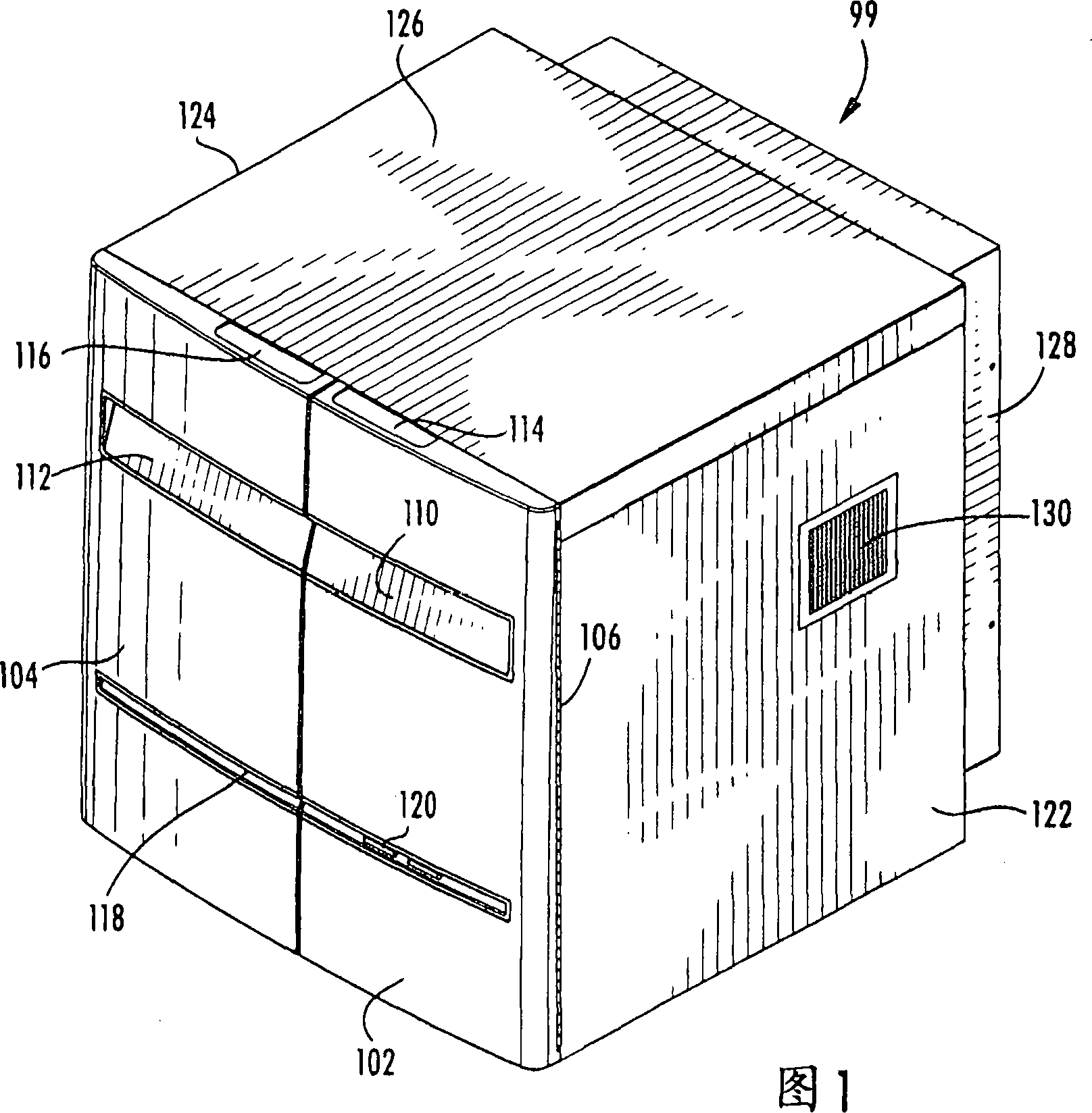
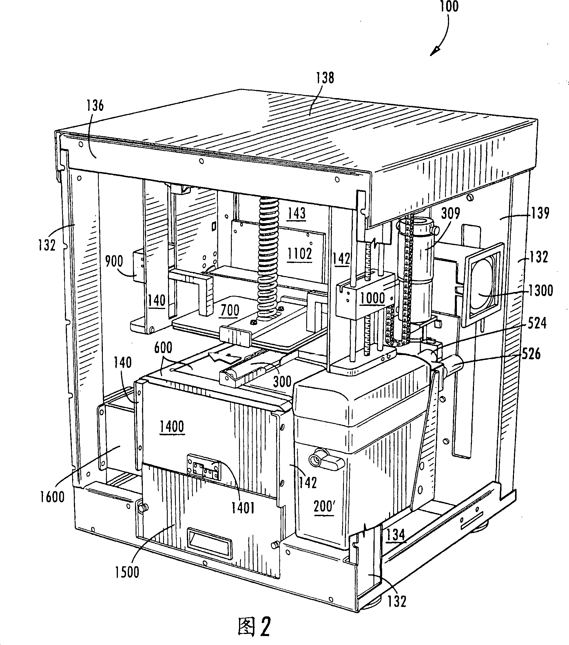
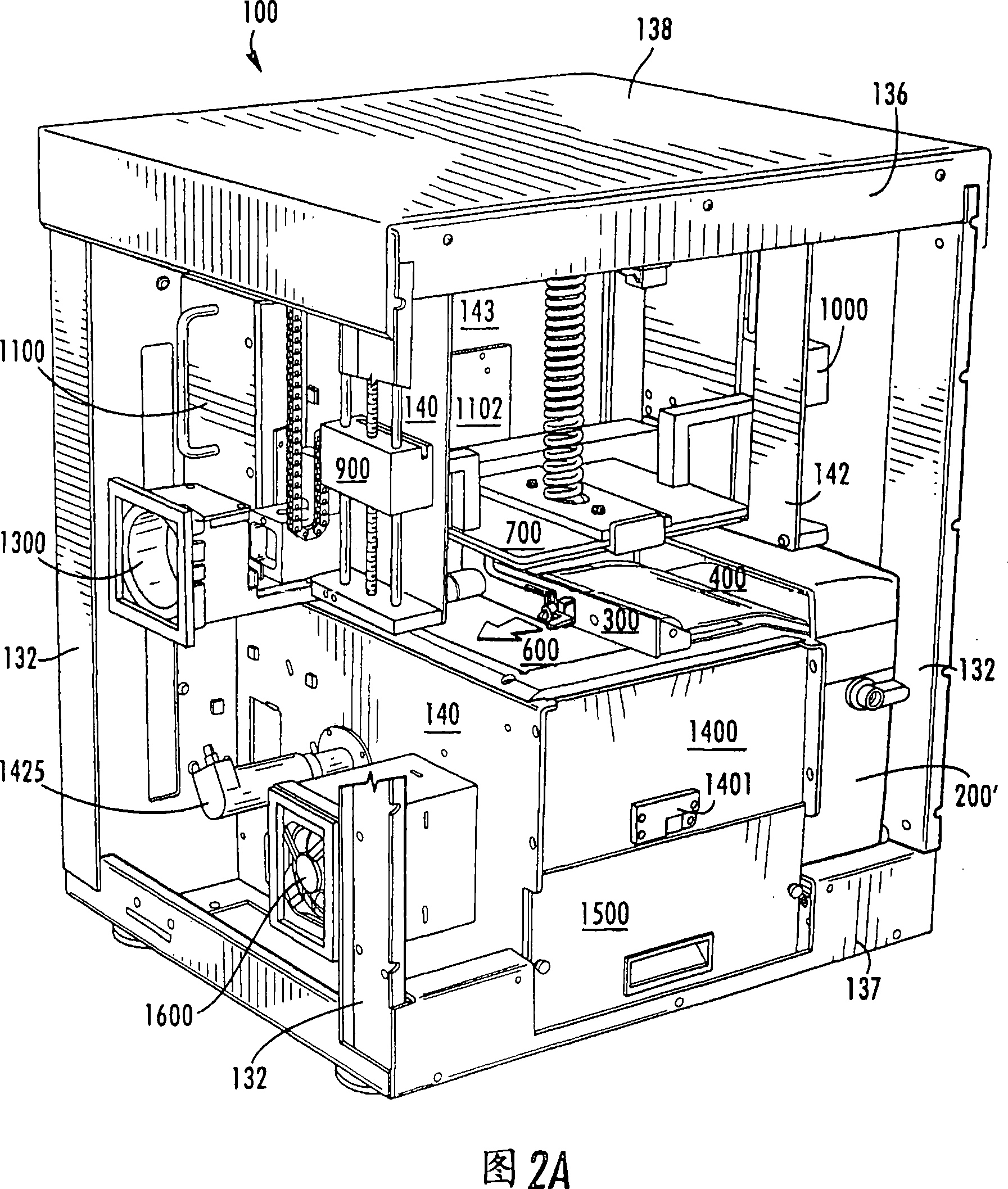
[0094] FIG. 1 shows generally at 99 in perspective view one embodiment of a housing for the table top modeler of the present invention. Housing 99 includes a right hand hinged door 102 and a left hand hinged door 104 . The hinges for the door 102 can be seen at 106 . The door 102 is provided with handles 110 and 114 on the front and top respectively, and the door 104 is provided with handles 112 and 116 on the front and top respectively. It should be appreciated that many such arrangements may be...


PUM


Abstract

A solid imaging device is provided that includes a replaceable cartridge containing a source of build material and an extendable and retractable flexible transfer membrane for layered transfer of build material from the cartridge to a surface of a construct in an image plane. Operators using the device can continue solid imaging with essentially no interruption simply by removing spent cartridges and replacing them with new ones. The device also includes the ability to withdraw and insert the imager without requiring a separate alignment step by the operator. Brushes attached to the transfer film and forming part of the cartridge are able to remove excess uncured build material intra-laminarly. If desired, the device can produce fully reacted constructs. A high intensity UV source cures the build between layers. Injection molded build pads are designed to hold the build in an inverted position for improved builds. The present invention also proposes tilting the structure elevator to reduce air entrapment and release the structure from the image plane.

Description

technical field [0001] The present invention relates to solid imaging devices and methods. Background technique [0002] Solid imaging devices have been used for rapid prototyping of product development models and, more recently, in manufacturing operations. Solid imaging devices typically produce three-dimensional objects from fusible powders or photocurable liquids by exposure to radiation in response to computer control. The data representing the thin cross-sectional layers of the three-dimensional object provides the computer with control parameters for a procedure that typically automates the building of the object in layers. A laser or other radiation source suitable for solid imaging sequentially irradiates individual thin layers of build material, in response to the layer-by-layer conversion of the material into a solid to create a solid imaged product. [0003] Solid imaging is sometimes referred to as "rapid prototyping" and includes different techniques such as ...

Claims


Application Information

Patent Timeline
IPC IPC(8): B29C67/00B22F3/105
Inventor C·R·斯佩里小丹尼斯·F·迈克纳马拉S·M·斯科特C·W·赫尔J·帕塔嫩M·穆杰德赫W·J·帕帕斯R·O·格雷戈里二世
Owner 3D SYST INC
Learn More