Pneumatic servobrake and diaphragm therefor

A pneumatic brake and booster technology, applied in the direction of brakes, brake transmissions, diaphragms, etc., can solve problems such as leaking, deterioration of diaphragm assembly, and no longer ensuring sealing, etc.

Active Publication Date: 2008-07-23
CONTINENTAL AUTOMOTIVE TECH GMBH
View PDF1 Cites 3 Cited by
  • Summary
  • Abstract
  • Description
  • Claims
  • Application Information

AI Technical Summary

Problems solved by technology

Studies have shown that this extrusion of the excess volume of the sealing bead leads to a deterioration of the diaphragm fit and the sealing of the two cavities by the diaphragm is no longer ensured
This leak will inevitably lead to failure of the brake booster

Method used


Image

  • Pneumatic servobrake and diaphragm therefor
  • Pneumatic servobrake and diaphragm therefor
  • Pneumatic servobrake and diaphragm therefor

Examples


Embodiment Construction

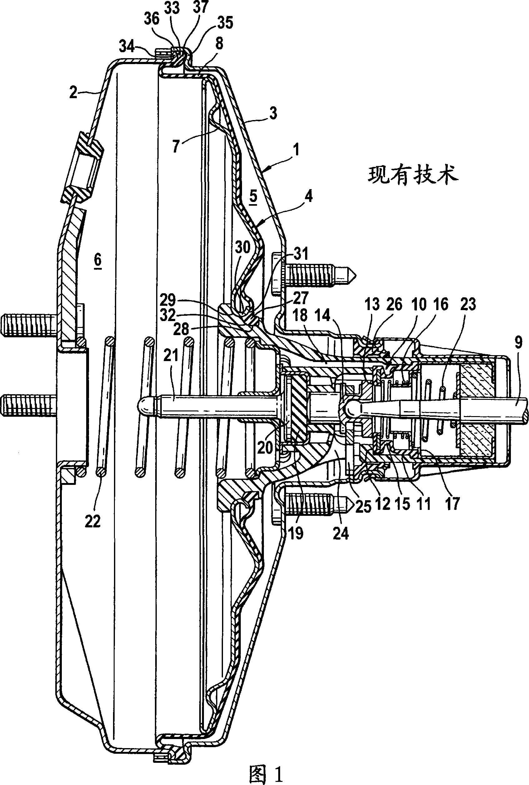
[0021] As shown in FIG. 1 , the only schematically indicated booster housing 1 of a prior art pneumatic brake booster for a motor vehicle braking system comprises a first housing half-cover 2 and a second housing half-cover 3 , so The two housing halves are pressed together force-fittingly by means of forming techniques, for example connected by recesses. The booster housing 1 is divided into a working chamber 5 and a low-pressure chamber 6 by an axially movable wall 4 . The axially movable wall 4 comprises a diaphragm 7, for example deep-drawn from sheet metal, and a flexible diaphragm 8 resting on the diaphragm, which is connected to the booster housing 1 at the outer periphery of the diaphragm 7. A rolling membrane is formed between them, which serves as a seal between the two chambers 5 , 6 and between the two chambers 5 , 6 and the environment.

[0022] A control valve 10 actuatable by an input 9 is arranged in a control housing 11 which is sealed in and guided by the bo...


PUM


Abstract

The invention relates to a pneumatic brake booster with a booster housing (1) comprising first and second housing halves (2, 3) and enclosed by an axially movable wall (4 ) is divided into a working chamber (5) and a low pressure chamber (6), and the pneumatic pressure difference acts on the movable wall, wherein the movable wall (4) is formed by the diaphragm (7) and rests on the diaphragm (7) Diaphragm (38; 47; 53) consisting of a radially inner bead (27) and a radially outer bead (39) for sealing the two cavities (5, 6) ; 48; 54), wherein the radially outer sealing bead (39; 48; 54) is clamped between the two shell halves (2, 3). In order to improve the clamping of the radially outer bead, it is proposed according to the invention that the radially outer bead (39; 48; 54) has a circumferentially uniform rib structure.

Description

technical field [0001] The invention relates to a pneumatic brake booster with a booster housing comprising first and second housing halves and divided into a working chamber and a low-pressure chamber by an axially movable wall, the pneumatic pressure A difference can act on this movable wall, wherein said movable wall consists of a diaphragm disk and a diaphragm resting on the diaphragm disk, which diaphragm has a radially inner seal for sealing the two cavities A bead and a radially outer sealing bead, wherein the radially outer sealing bead is clamped between the two shell halves. Background technique [0002] A pneumatic brake booster of this type is known, for example, from DE 41 24 683 A1. The radially outer sealing bead of the conventional brake booster is clamped between two substantially radially formed flanges of the two housing halves, wherein the radially protruding flanges of the second housing half Formed on the rim is an axially designed flange which protru...

Claims


Application Information

Patent Timeline
Patent Type & Authority Applications(China)
IPC IPC(8): B60T13/569F16J3/02
CPCF16J3/02B60T13/569
Inventor J·法勒R·雅各比
Owner CONTINENTAL AUTOMOTIVE TECH GMBH
Why Eureka
Try Eureka