
Corrugated sternum H-shaped steel composite beam

A technology of corrugated webs and composite beams, applied to structural elements, building components, and elongated structural components for load-bearing, etc., can solve the problems that traditional products are difficult to meet the requirements, the design and construction are complicated, and the construction speed is affected. , to achieve the effect of beautiful weld seam without spatter, excellent light weight and excellent anti-fatigue performance

Inactive Publication Date: 2008-07-23
TONGJI UNIV
View PDF1 Cites 38 Cited by
  • Summary
  • Abstract
  • Description
  • Claims
  • Application Information

AI Technical Summary

Problems solved by technology

Welded H-beams have the same problem, so it is necessary to limit the height-thickness ratio of the web during design, resulting in a thicker web thickness, so the amount of steel used is too large
In addition, when using welded H-beams, special technical measures must be taken, such as stiffeners or using the strength of the web after buckling, etc., the design and construction are more complicated
[0005] Due to the limitations of processing technology and processing equipment, traditional hot-rolled I-beams and H-beams are difficult to achieve large-scale products. When the required load-bearing capacity and rigidity are large, traditional products are difficult to meet the requirements
If it is completed by designing, processing and welding H-shaped steel, it will be labor-intensive and time-consuming, increase the cost, and affect the construction speed

Method used


Image

  • Corrugated sternum H-shaped steel composite beam
  • Corrugated sternum H-shaped steel composite beam

Examples


Embodiment 1

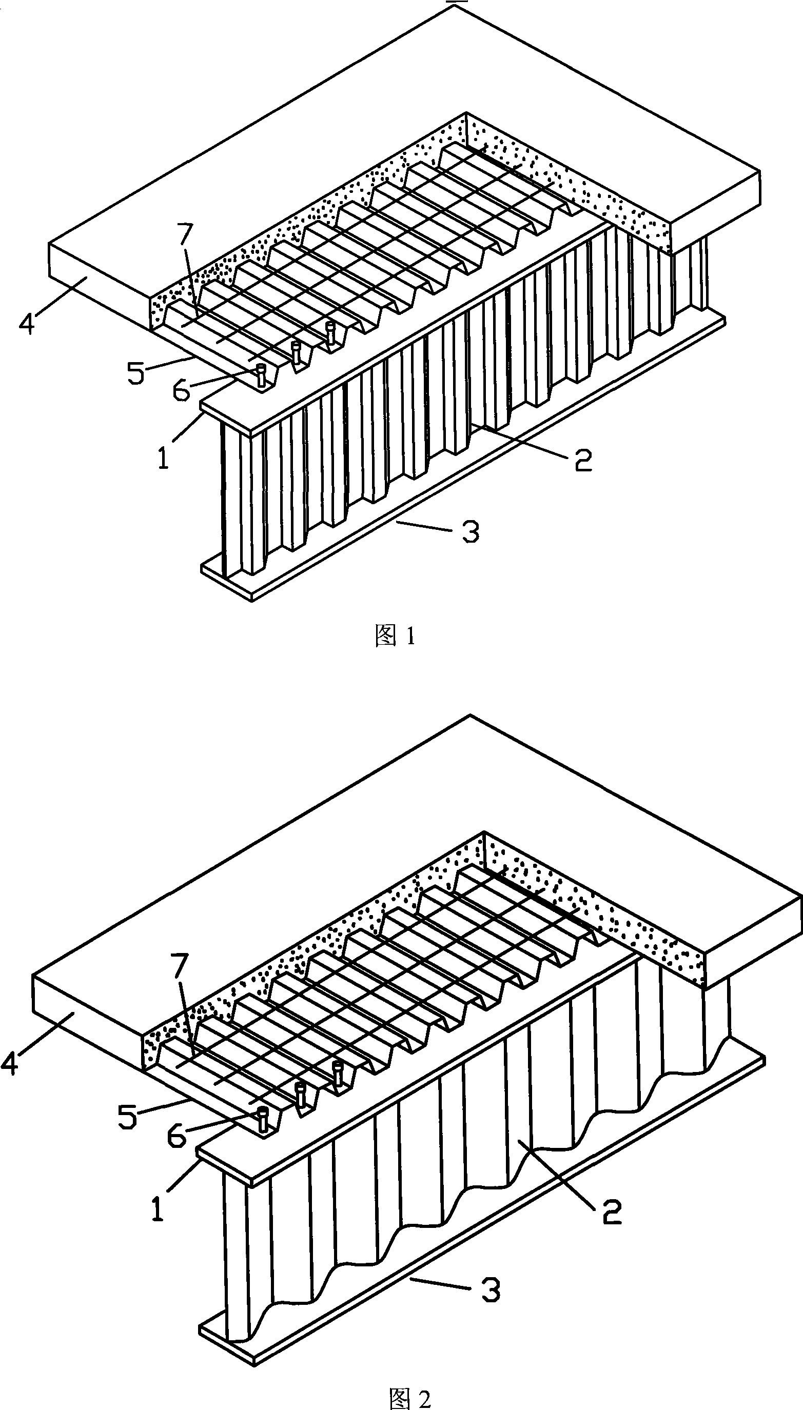
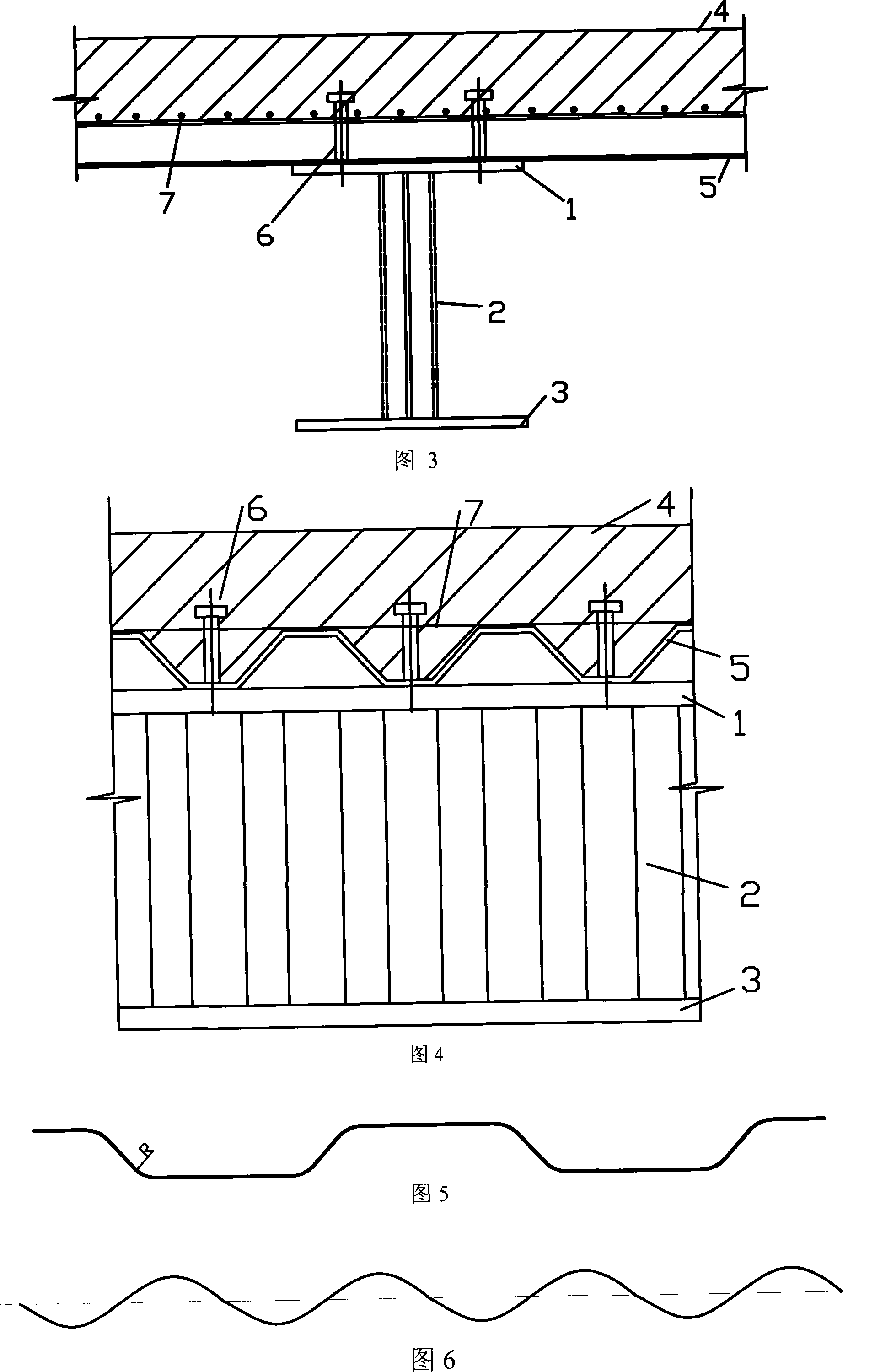
[0032] Example 1: The cross-section shape of the H-shaped steel composite beam with corrugated web is composed of the middle web 2, the upper flange 1, and the lower flange 3. The upper flange 1 is parallel to the lower flange 3, and the web 2 is vertical. On the upper flange 1 and the lower flange 3, the web 2 is a corrugated steel plate with a trapezoidal cross-sectional shape, and the inclination angle of the inclined section is 58°. The reinforced concrete wing plate 4 is located above the profiled steel plate 5, the profiled steel plate 5 is located above the upper flange 1, the reinforced concrete wing plate 4, the profiled steel plate 5, and the upper flange 1 are fixed by the tack 6, and the transverse reinforcement 7 Welded on the profiled steel plate 5 tops.

[0033] In order to verify the performance of the device, a test piece was made for research. The steel materials in the test piece are all made of Q235 steel, the thickness of the reinforced concrete wing plat...


PUM


Abstract

The invention relates to a corrugated web plate H-shaped profile steel composite bean, belonging to the technical field of building profile materials . The cross section port type comprises a corrugated web plate and an upper and lower flange joints. The upper flange is in parallel with the lower flange; the web plate is vertical to the upper flange and the lower flange; the web plate is connected with the flanges by single-sided fillet weld; the web plate is a trapezoid ripple or a sine curve ripple, wherein the lengthwise direction of the trapezoid ripple is repeated periodically. The upper part of a composite beam is a reinforced concrete swing plate and a profiled steel sheet. The upper flange, the reinforced concrete plate and the profiled steel sheet are connected by a plurality of studs; the reinforced concrete swing plate can be connected with the profiled steel sheet by additional lateral steel bar. The traditional hot-rolling joist steel and H-shaped profile steel composite beam can be replaced by the corrugated web plate H-shaped profile steel composite bean which has the wider application than joist steel and H-shaped profile steel composite beam; the maximization can be realized for special field and special location comprising the construction of large span industrial and civil building and large span bridge.

Description

technical field [0001] The invention belongs to the technical field of building profiles, in particular to an H-shaped steel composite beam with a corrugated web. Background technique [0002] At present, ordinary hot-rolled I-beams, hot-rolled H-beams and welded H-beam composite beams are commonly used in similar fields. The lower steel beam and the upper reinforced concrete slab are composed of load-bearing members through shear connectors. Steel beams generally use hot-rolled I-beams, hot-rolled H-beams and welded H-beams. This design can be seen in the patent—composite beam (ZL 95195718.X). [0003] Ordinary hot-rolled I-beams and H-beams are hot-rolled in the factory. Due to the limitation of processing technology, their webs must be straight plates. The welded H-shaped steel is to weld two flange plates and a plane web together to form an H-shaped section. When the specifications of the hot-rolled steel cannot meet the requirements, welded H-shaped steel can be used....

Claims


Application Information

Patent Timeline
Patent Type & Authority Applications(China)
IPC IPC(8): E04C3/293
Inventor 李国强孙飞飞张哲杨涛春胡大柱刘桂然
Owner TONGJI UNIV
Learn More