Spinning drawing-out drafting machine
A technology of drafting and drafting area, applied in the field of spinning drawing frame drafting mechanism, can solve the problems of poor versatility, inability to meet the needs of testing and small batch production, etc., achieve enhanced control, increase the adjustment range, and improve drafting efficiency effect
- Summary
- Abstract
- Description
- Claims
- Application Information
AI Technical Summary
Problems solved by technology
Method used
Image
Examples
Embodiment 1
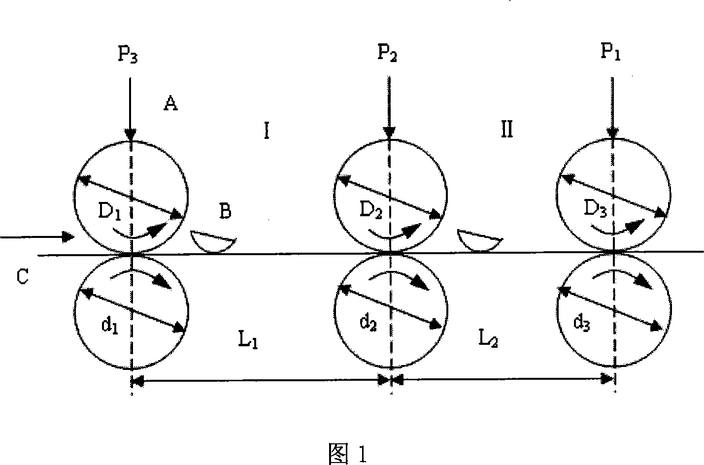
[0022] As shown in Fig. 1, a kind of spinning drawing frame drafting mechanism is composed of roller-type drafting mechanism A and semi-arc pressure bar B, and described roller-type drafting mechanism A is composed of three sets of rollers, top roller pairs Composition, divided into rear drafting zone I composed of middle and rear rollers and top rollers and front drafting zone II composed of front, middle rollers and top rollers. Diameter d of front, middle and rear rollers 1 、d 2 、d 3 Both are 35mm; three top rollers D 1 、D 2 、D 3 The diameter is 38mm. The semi-arc pressure bars B are respectively installed in the rear drafting zone I and the front drafting zone II, and can be easily disassembled as required. Because the pressure bar B that helps to control the movement of fibers is added in the rear drafting area, the drafting ratio of the rear area can be greatly increased to 2.5, thus significantly improving the drafting efficiency. The drafting ratio of the front a...
Embodiment 2
[0029] As shown in Fig. 1, a kind of spinning drawing frame drafting mechanism is composed of roller-type drafting mechanism A and semi-arc pressure bar B, and described roller-type drafting mechanism A is composed of three sets of rollers, top roller pairs Composition, divided into rear drafting zone I composed of middle and rear rollers and top rollers and front drafting zone II composed of front, middle rollers and top rollers. Diameter d of front, middle and rear rollers 1 、d 2 、d 3 Both are 35mm; three top rollers D 1 、D 2 、D 3 The diameter is 39mm. The draft ratio of the rear area is 3, and the draft ratio of the front area is 5; the center distance between the middle and rear rollers is L 1 100mm; center distance L between front and middle rollers 2 110mm, pressurized P on the front top roller 1 , the pressure P on the middle top roller 2 and pressurized P on the rear top roller 3 They are respectively adjusted within the range of 900N, 700N, and 700N, and the...
Embodiment 3
[0036] As shown in Figure 1, a spinning drawing frame drafting mechanism is composed of a roller-type drafting mechanism A and a semi-arc pressure bar B. The roller-type drafting mechanism A consists of three sets of rollers and a pair of top rollers. Composition, divided into rear drafting zone I composed of middle and rear rollers and top rollers and front drafting zone II composed of front, middle rollers and top rollers. Diameter d of front, middle and rear rollers 1 、d 2 、d 3 Both are 35mm; three top rollers D 1 、D 2 、D 3 The diameter is 40mm. The draft ratio of the rear area is 2.5, and the draft ratio of the front area is 5; the center distance between the middle and rear rollers is L 1 95mm; center distance L between front and middle rollers 2 is 100mm, the pressure P on the front top roller 1 , the pressure P on the middle top roller 2 and pressurized P on the rear top roller 3 Adjusted within the range of 1000N, 700N, and 700N respectively, the output speed...
PUM
 Abstract
Description
Claims
Application Information
 - R&D
- Intellectual Property
- Life Sciences
- Materials
- Tech Scout
- Unparalleled Data Quality
- Higher Quality Content
- 60% Fewer Hallucinations
Browse by: Latest US Patents, China's latest patents, Technical Efficacy Thesaurus, Application Domain, Technology Topic, Popular Technical Reports.
© 2025 PatSnap. All rights reserved.Legal|Privacy policy|Modern Slavery Act Transparency Statement|Sitemap|About US| Contact US: help@patsnap.com


