
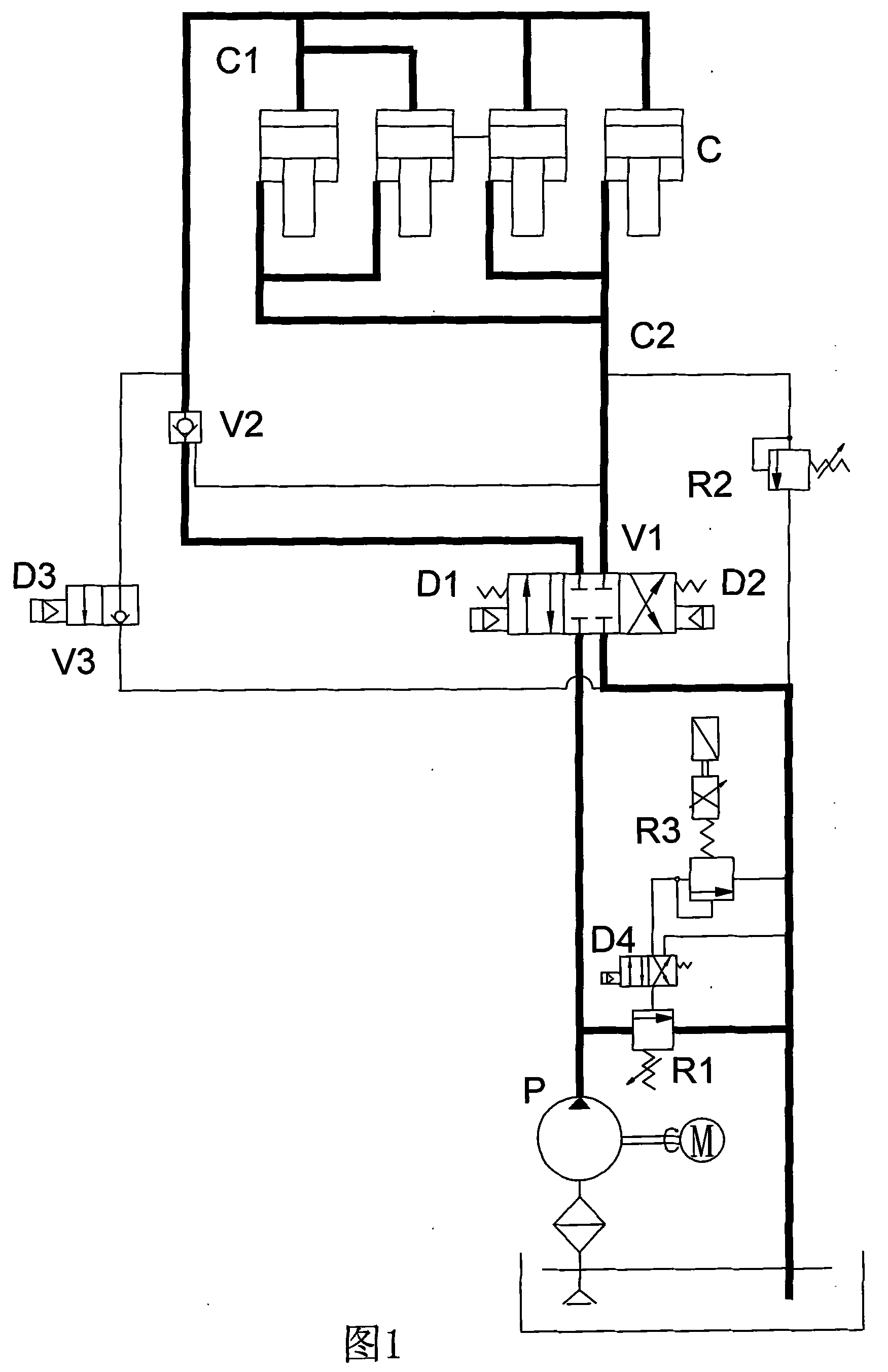
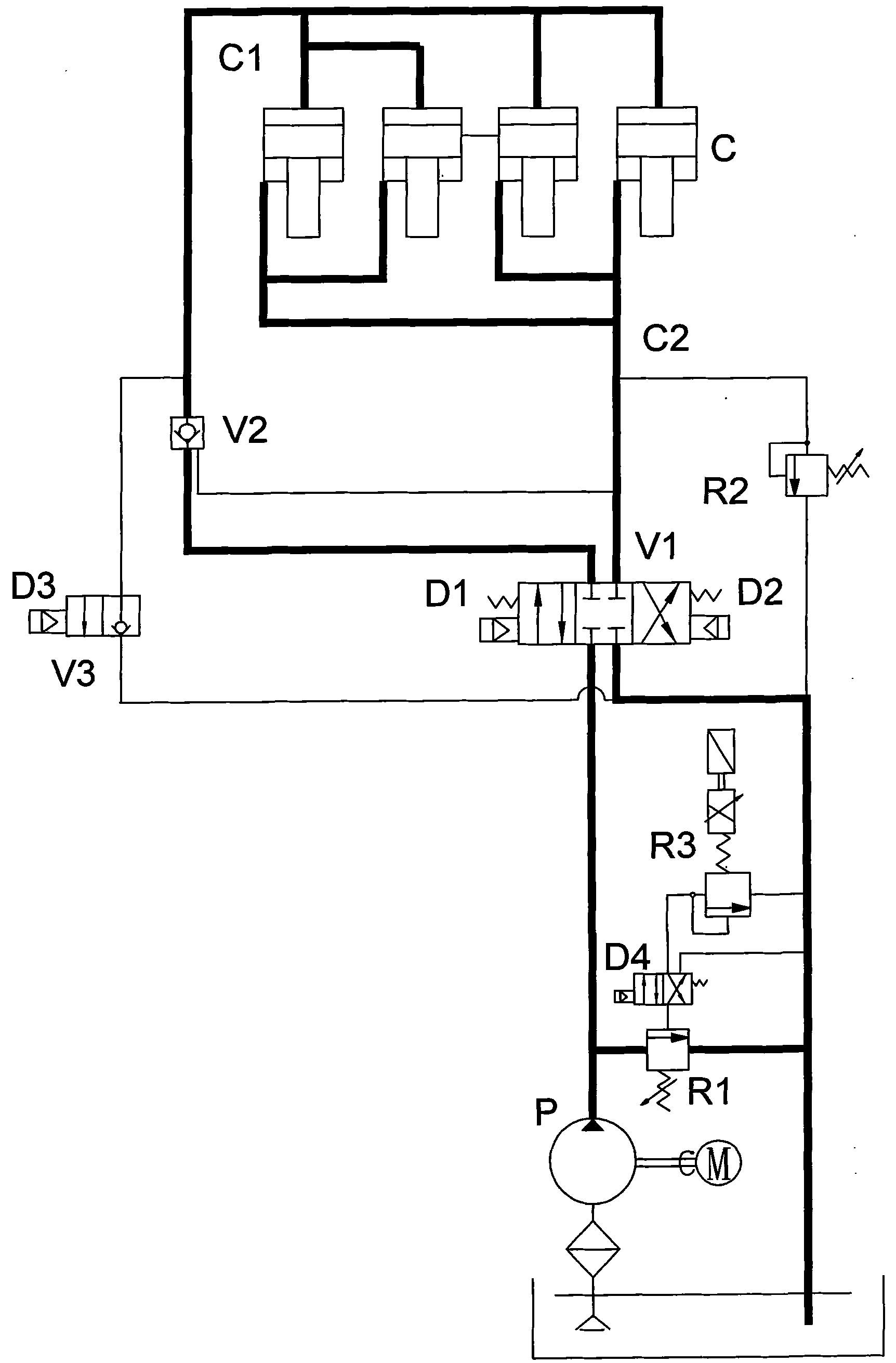
High pressure model-locked loop of double movable plate direct press injection machine

A direct pressure, injection molding machine technology, applied in the field of high pressure mold locking circuit, can solve the problems of high pressure commutation impact, large leakage, etc., to achieve the effect of system simplification and convenient adjustment

Inactive Publication Date: 2011-01-19
广东佳明机器有限公司
View PDF0 Cites 0 Cited by
  • Summary
  • Abstract
  • Description
  • Claims
  • Application Information

AI Technical Summary

Problems solved by technology

[0005] In the present invention, an electromagnetic reversing valve is used to switch the high-pressure / resetting action of the high-pressure mold-clamping oil cylinder. Aiming at the disadvantage of large leakage in the general slide valve-type reversing valve, one of the working oil ports of the electromagnetic reversing valve and the high-pressure mold-clamping oil cylinder A hydraulically controlled one-way valve is connected in series between the high-pressure chambers to keep the pressure; at the same time, because the general electromagnetic reversing valve has the problem of large high-pressure reversing impact, an electromagnetic switch valve is connected to the high-pressure cavity of the high-pressure clamping cylinder for pressure relief before reset.

Method used


Image

  • High pressure model-locked loop of double movable plate direct press injection machine
  • High pressure model-locked loop of double movable plate direct press injection machine

Examples


Embodiment Construction

[0009] The present invention will be described in further detail below in conjunction with the accompanying drawings.

[0010] Such as figure 1 As shown, the electric motor M drives the oil pump P, and the oil outlet of the oil pump is connected to the electromagnetic reversing valve V1, and then all the way is connected to the positive oil inlet of the hydraulic control check valve V2, and the forward oil outlet of the hydraulic control check valve V2 is connected to the high-pressure mold clamping Cylinder C is connected with rodless cavity C1; the other is connected with high pressure clamping cylinder C with rod cavity C2. The rodless chamber C1 of the high pressure clamping cylinder C is connected with the normally closed electromagnetic switch valve V3, and the oil return end of the electromagnetic switch valve V3 is connected with the oil tank. The high-pressure clamping cylinder C has a rod chamber C2 connected to a relief valve R2, and the oil outlet of the relief va...


PUM


Abstract

The invention relates to a high pressure die-locking circuit of a dual-motion plate direct pressure injection machine, comprising an oil pump which is driven by an electric motor, an electromagnetic reversing valve, an electromagnetic switch valve, overflow valves, a hydraulic control check valve and a high pressure die-locking oil cylinder; the electric motor drives the oil pump; the oil outlet of the oil pump is connected with the electromagnetic reversing valve; one working oil nozzle of the electromagnetic reversing valve is connected with the high pressure chamber of the high pressure die-locking oil cylinder through the hydraulic control check valve; another working oil nozzle of the electromagnetic reversing valve is connected with the recovery chamber of the high pressure die-locking oil cylinder; the oil outlet of the oil pump and the recovery chamber of the high pressure die-locking oil cylinder are both provided with the overflow valves; the non-rod chamber of the high pressure die-locking oil cylinder is connected with an oil tank through the electromagnetic switch valve. The proposal sufficiently considers the working characteristics of the dual-motion direct pressinginjection machine and optimizes and simplifies the high pressure die-locking control oil path, and the invention is the high pressure die-locking circuit of the dual-motion direct pressing injection machine with more reasonable structure.

Description

technical field [0001] The invention relates to a high-pressure mold-clamping circuit of a double-moving-plate direct-pressure injection molding machine. Background technique [0002] The existing double-moving platen direct pressure injection molding machine high-pressure clamping circuit generally has a complex structure and many system components, which easily brings a series of problems, such as many system action steps, resulting in long action cycles; due to the number of system components There are many, which will easily increase the leakage of the system, resulting in unreliable pressure maintenance. In addition, the design of the oil circuit block is cumbersome, the workload of pipe layout is heavy, the quality requirements of maintenance and machine operators are high, and the system maintenance is also troublesome. Contents of the invention [0003] The purpose of the present invention is to overcome the deficiencies of the prior art, to provide a double-moving...

Claims


Application Information

Patent Timeline
Patent Type & Authority Patents(China)
IPC IPC(8): B29C45/67
Inventor 李裔强
Owner 广东佳明机器有限公司
Learn More