
Method and device for automatically controlling lamps

A controlled and chip-controlled technology, applied in lighting devices, lamp circuit layout, light sources, etc., can solve problems such as complex hardware structure, difficult control line construction, and maintenance, and achieve the effect of convenient operation and low cost

Inactive Publication Date: 2008-07-16
SHANGHAI AISAIKE COMP TECH
View PDF0 Cites 19 Cited by
  • Summary
  • Abstract
  • Description
  • Claims
  • Application Information

AI Technical Summary

Problems solved by technology

[0003] The purpose of the present invention is to provide a method and device for automatically controlling lamps, which mainly solve the problem that if the number of lamps is large in the existing method, the number of computer output terminals and control lines increases, and the hardware structure is very complicated; Wide, the length of the control line will be very long, and many and long control lines make construction and maintenance very difficult and other technical problems, which is conducive to controlling a large number of lights at low cost

Method used


Image

  • Method and device for automatically controlling lamps
  • Method and device for automatically controlling lamps
  • Method and device for automatically controlling lamps

Examples


Embodiment Construction

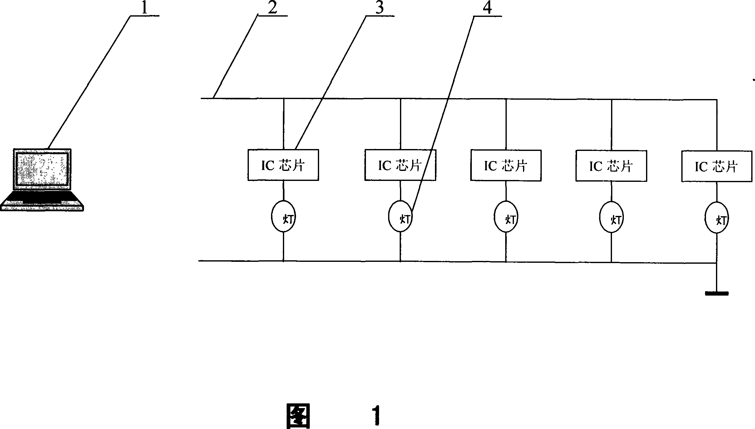
[0027] Please see Figure 1, the computer 1 sends wireless codes of automatic control information to the air through the wireless network card, each group of automatic control information codes is 32 bits, the first 16 bits are address codes, and the last 16 bits are operation codes. Within the effective receiving range of the signal transmitted by the wireless network card, all IC chips 3 can receive the wireless automatic control information code.

[0028] Computer 1 is a computer with a wireless network card, such as TinkPad R60, which uses an Intel PRO / Wireless 2200BG wireless network card.

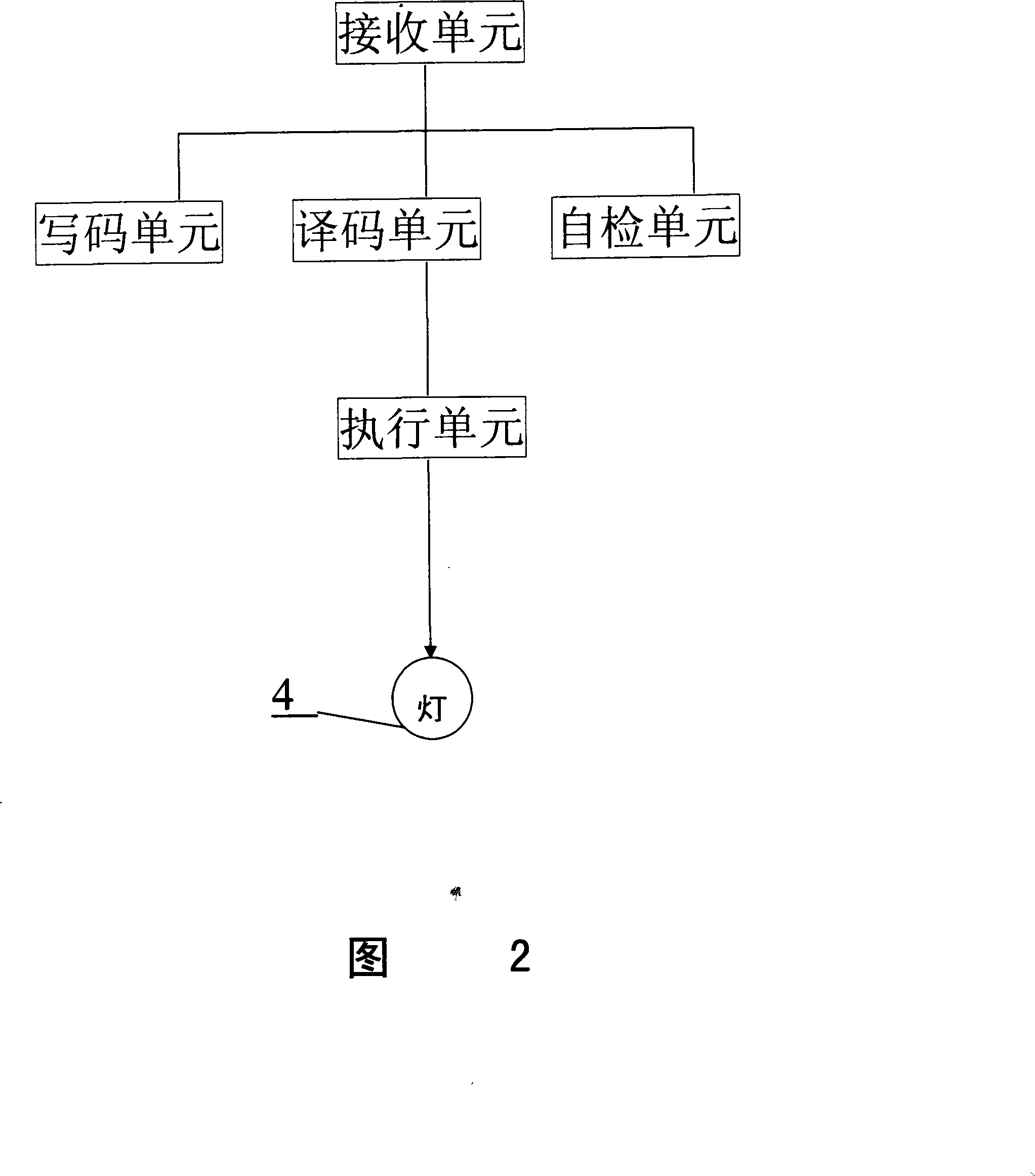
[0029] Please see Fig. 2 again, Fig. 2 is a block diagram of the working principle of the IC chip 3. The IC chip 3 is composed of five parts: a receiving unit, a code writing unit, a decoding unit, a self-checking unit and an executing unit.

[0030] The receiving unit of the IC chip 3 receives the wireless signal of the instruction code sent by the computer 1 .

[0031] The code wri...


PUM


Abstract

The invention relates to a method and a device for automatically controlling lamps. The method is as follows: the IC chips connected with each lamp are automatically controlled by a computer capable of transmitting wireless signals through a wireless LAN. Efficient range for receiving signals transmitted by the wireless LAN is required to cover the area where the controlled lamps are laid out. The device comprises a wireless LAN control system which consists of a computer and a wireless LAN adapter, an IC chip capable of receiving the wireless control signals and a lamp connected with the IC chip. The invention is mainly aimed at dealing with problems in the prior method that if the number of the lamps is increased, the number of output ends and control lines increases at the same time, which complicates the hardware structure; if the coverage of lamps is enlarged, the length of control lines is lengthened, and too much and long control lines brings technical difficulties in construction and maintenance. The invention is advantageous to control a great number of lamps at lower cost.

Description

technical field [0001] The invention relates to a method and device for automatically controlling lamps, in particular to a method for automatically controlling lamps using a wireless local area network and a device for realizing the automatic control method. Background technique [0002] The existing technology of automatically controlling the lamp is to use the output terminal of the computer to control the on, off, brightness and color state changes of the lamp. The computer outputs instructions to the output terminal to make the relays, thyristors, silicon controlled rectifiers, potentiometers and other actuators installed at the output port act. The changes of the actuators are transmitted to the lamp through the control line to realize the on, off, brightness and color status of the lamp. Variety. If the number of lights is large, the number of computer output terminals and control lines will increase, and the hardware structure will be very complicated; if the lights...

Claims


Application Information

Patent Timeline
Patent Type & Authority Applications(China)
IPC IPC(8): H05B37/02G08C17/02
Inventor 白英彩金起农金健
Owner SHANGHAI AISAIKE COMP TECH
Learn More