
Positive and reverse rotation control circuit of electric motor

A technology for controlling circuits and motors, which is applied in the direction of motor starters, circuits, motor generators/starters, etc., and can solve the problem of increased cost of control circuits, increased number of relay circuits, and control circuit costs of electric door lock systems Increase and other problems, to achieve the effect of low cost and prevent damage to wiring

Inactive Publication Date: 2008-07-16
HONDA MOTOR CO LTD
View PDF0 Cites 9 Cited by
  • Summary
  • Abstract
  • Description
  • Claims
  • Application Information

AI Technical Summary

Problems solved by technology

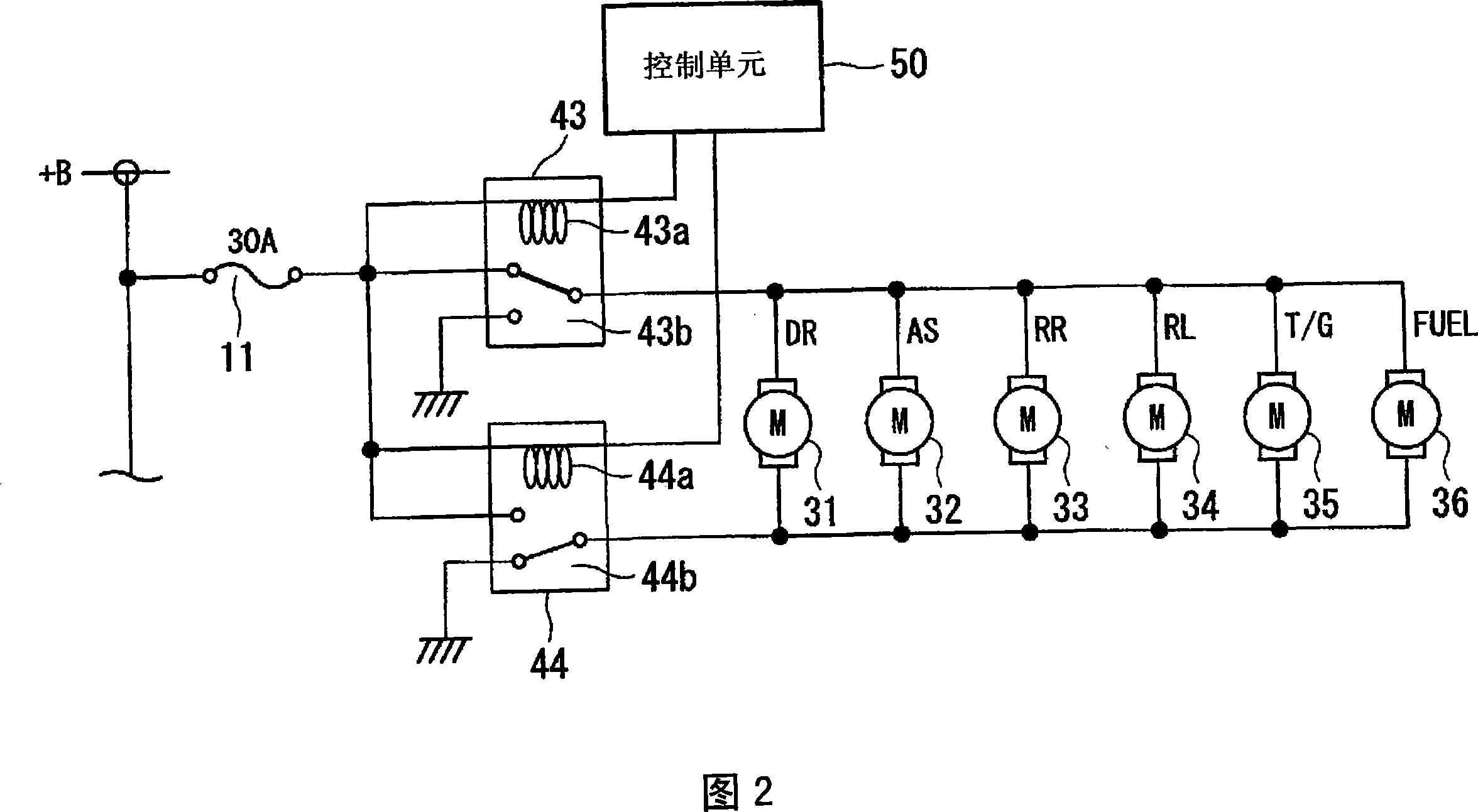
Therefore, since long and expensive wiring must be used, there is a problem that the cost of the control circuit of the electric door lock system increases.
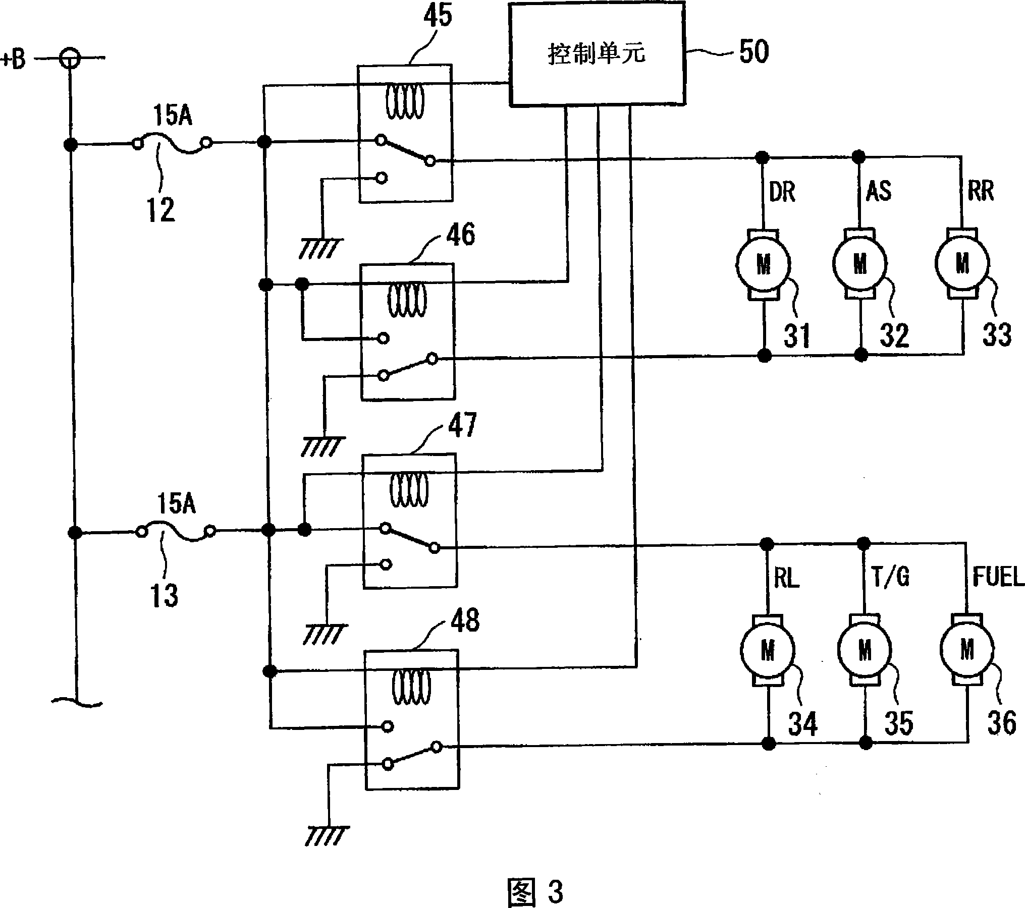
[0009] In addition, in the above control circuit of Fig. 3, since the current capacity of the wiring used is 15A, it is cheaper than that of Fig. 2, but since the number of necessary relay circuits increases, an electric door lock system is still produced The problem of increased cost of the control circuit

Method used


Image

  • Positive and reverse rotation control circuit of electric motor
  • Positive and reverse rotation control circuit of electric motor
  • Positive and reverse rotation control circuit of electric motor

Examples


Embodiment Construction

[0022] Hereinafter, embodiments of the present invention will be described in detail with reference to the drawings.

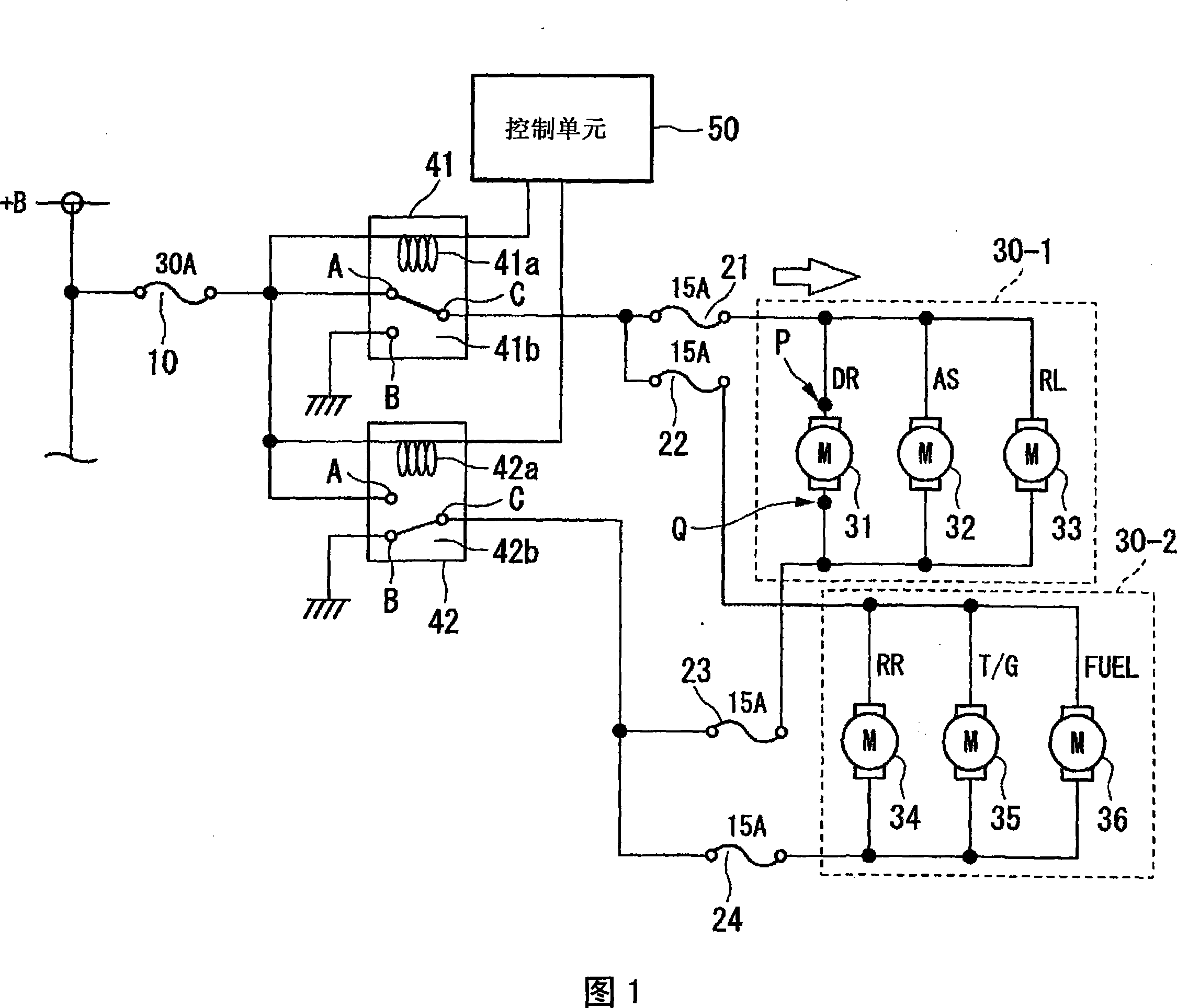
[0023] FIG. 1 shows the configuration of a motor forward and reverse rotation control circuit 1 according to an embodiment of the present invention. The motor is used here to unlock or lock the opening and closing body of the door for getting on and off the car, and the control circuit 1 of FIG. Lock / unlock.

[0024] The control circuit 1 includes a total of six motors 31 to 36 for opening and closing the opening and closing bodies. The motors 31 to 36 for opening and closing the above-mentioned opening and closing bodies are respectively connected to the opening and closing of the driver's door DR, the passenger's door AS, the rear left door RL, the rear right door RR, the tailgate TG, and the fuel inlet cover FUEL. The bodies are arranged correspondingly, and the corresponding opening and closing bodies are locked and unlocked through the forward / reverse r...


PUM


Abstract

The present invention provides a forward and reverse control circuit of an electric motor, in which a plurality of motors (31-36) for opening and closing bodies are connected to a plurality of motor groups (the first motor group 30-1, the second motor group 30-2 ) are connected to the relay circuits (41) and (42) through the second fuses (21-24) with a current capacity value smaller than that of the first fuse (10), and the current capacity value is lower than that of the first fuse ( 10) Small wiring between the second fuses (21-24) connects each second fuse (21-24) and each switch body opening and closing motor (31-36). Therefore, it is possible to realize a forward and reverse control circuit of a motor that can be used in an electric door lock system of an automobile at low cost.

Description

technical field [0001] The present invention relates to a forward and reverse control circuit of a motor for controlling switching between forward rotation and reverse rotation of the motor. Background technique [0002] Conventionally, a component composed of a control circuit shown in FIG. 2 or FIG. 3 is used as an electric door lock system installed in an automobile. [0003] In FIG. 2 , corresponding to each opening and closing body of the driver's seat door DR, the passenger's seat door AS, the rear left door RL, the rear right door RR, the tail gate (tail gate) TG, and the fuel inlet cover FUEL. The six switch body opening and closing motors 31 to 36 are connected in parallel to two relay circuits 43 and 44 via a common wiring, and the relay circuits 43 and 44 are connected to the positive terminal +B of the power supply through a fuse 11 . The control unit 50 controls the energization / non-energization of the coils 43a and 44a to switch between the terminals AC of the...

Claims


Application Information

Patent Timeline
Patent Type & Authority Applications(China)
IPC IPC(8): H02P1/54H02P1/56H01H47/00
Inventor 小滨纪宏
Owner HONDA MOTOR CO LTD
Learn More