Disk unit
An optical disc device and optical disc technology, which are applied in the directions of recording information storage, instruments, etc., can solve the problem of inability to take out small-diameter optical discs.
- Summary
- Abstract
- Description
- Claims
- Application Information
AI Technical Summary
Problems solved by technology
Method used
Image

Examples
Embodiment 1
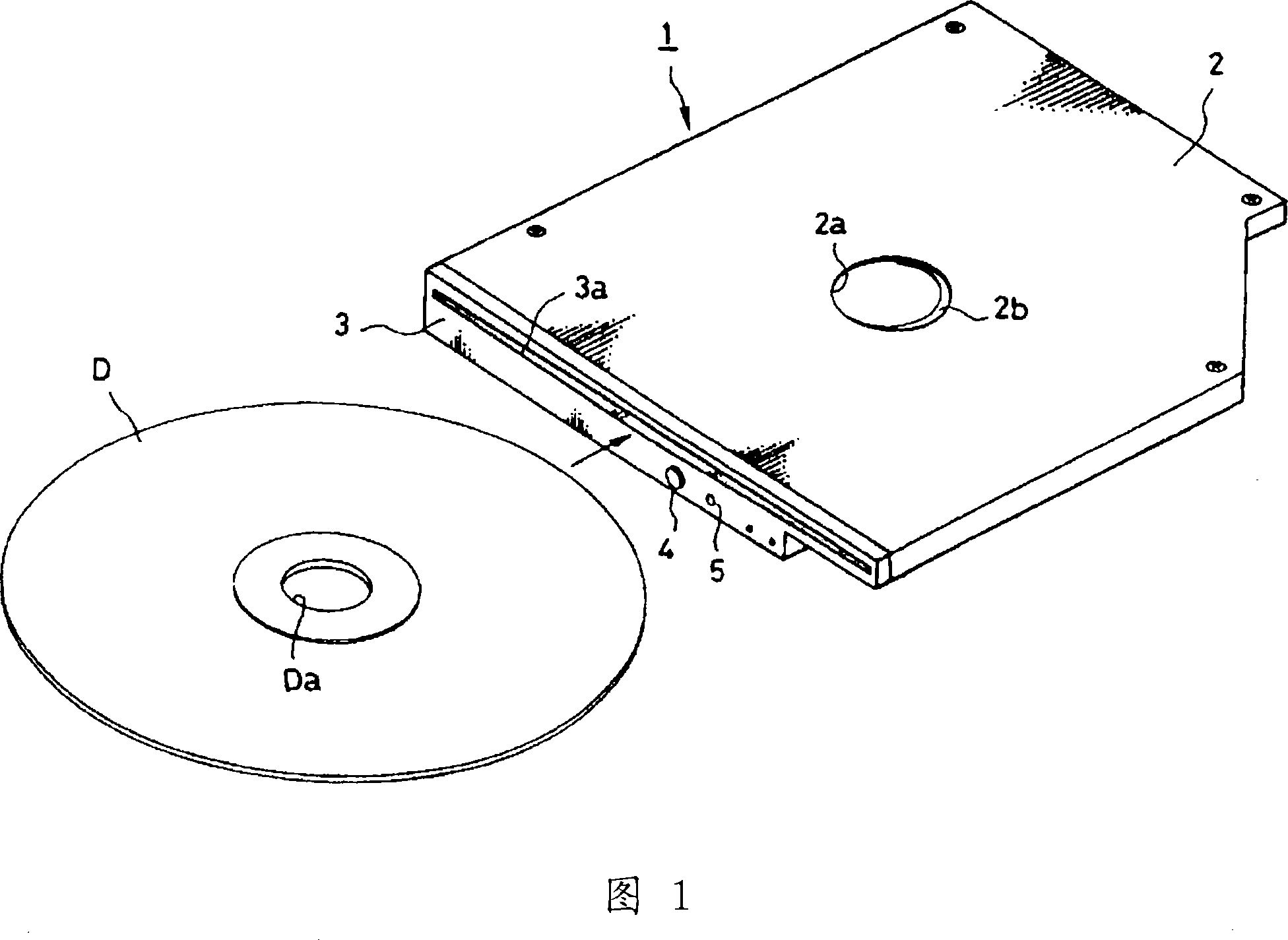
[0154] 1 shows an external view of a chuck-type optical disc device 1 implementing the present invention. An opening 2a is formed in the center of the top plate of the casing 2 constituting an isolated state, and a convex portion 2b protruding inward is formed on the opening peripheral portion of the opening 2a. . A front cover 3 is fixed at the front end of the casing 2, and the front cover 3 is provided with an insertion port 3a for inserting an optical disc D (the first disc-shaped recording medium) with a prescribed outer diameter (specifically, a diameter of 12 cm); The button 4 is used to instruct to unload the optical disk D stored inside the device and the indicator 5 is used to display the operation state of the optical disk device 1 .
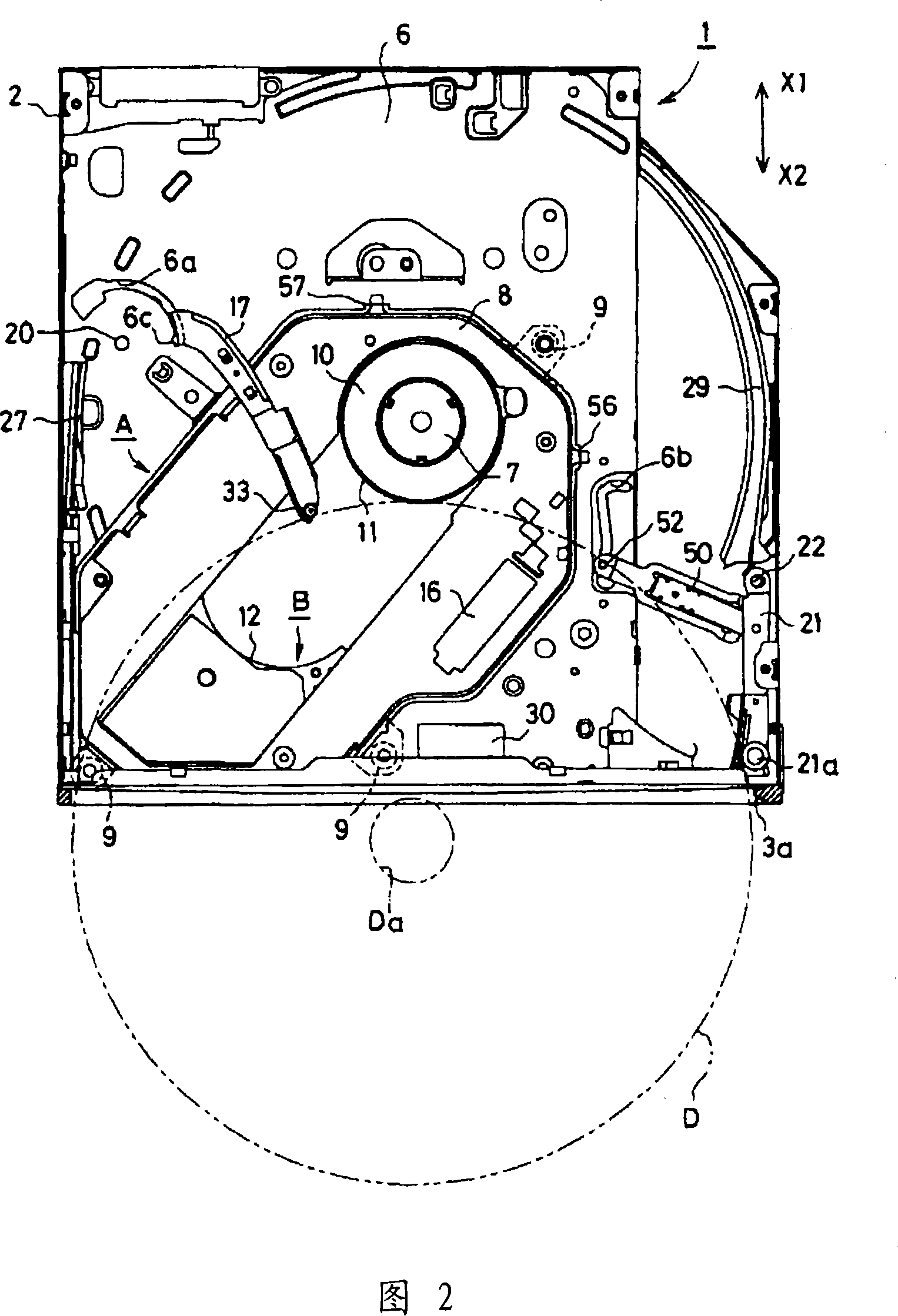
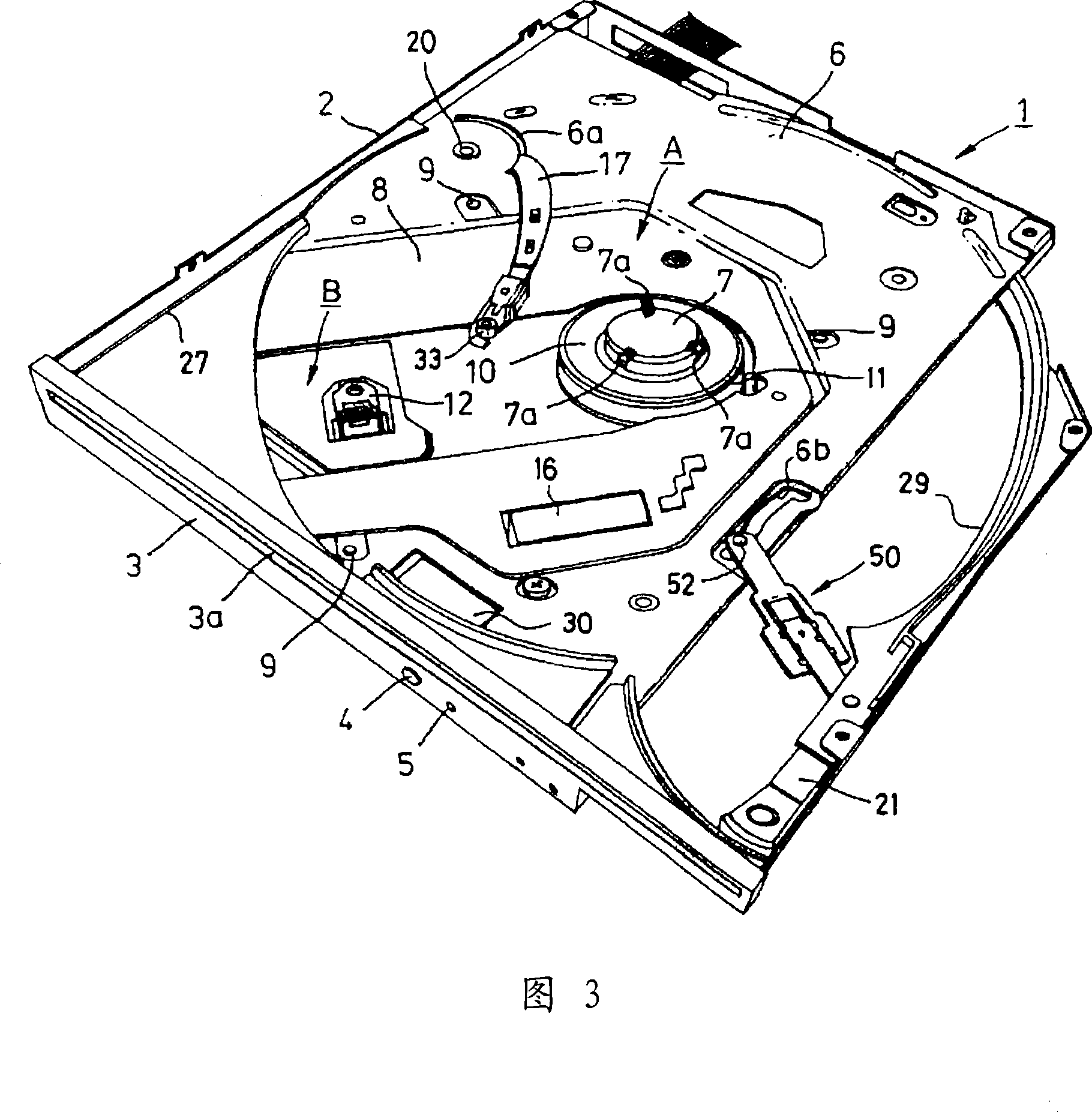
[0155] FIG. 2 is a plan view showing a state where the top plate portion of the casing 2 of the optical disc device 1 is removed, and FIG. 3 is a perspective view thereof. A bottom plate 6 is arranged inside the casing 2, and a recor...
Embodiment 2
[0191] Next, Embodiment 2 of the present invention will be described below. FIG. 19 is a plan view of the optical disk drive 1 in a state where the top plate portion of the casing 2 is removed. In Fig. 19, symbol 17 is the disc support arm in charge of the action of guiding the disc D to the inside of the device and pushing out the disc D with a diameter of 12 cm to the outside of the device. A stopper 19 is installed at its front end. When a small diameter disc other than the 12 cm disc is inserted by mistake, specifically In the case of the disc Ds with a diameter of 8 cm, it is used to prevent misinsertion and prevent access to the inside of the device. In addition, since the drive mechanism for swinging the disc support arm 17 is the same as the arm drive mechanism C used in the first embodiment, its description is omitted.
[0192] In this stopper 19, as shown in FIG. 20, an abutment portion 19a that contacts the front peripheral edge of the 8cm optical disc Ds is attach...
PUM
 Abstract
Description
Claims
Application Information
 - Generate Ideas
- Intellectual Property
- Life Sciences
- Materials
- Tech Scout
- Unparalleled Data Quality
- Higher Quality Content
- 60% Fewer Hallucinations
Browse by: Latest US Patents, China's latest patents, Technical Efficacy Thesaurus, Application Domain, Technology Topic, Popular Technical Reports.
© 2025 PatSnap. All rights reserved.Legal|Privacy policy|Modern Slavery Act Transparency Statement|Sitemap|About US| Contact US: help@patsnap.com