Passive relay antenna

A technology for repeaters and antennas, applied in the field of passive repeater antennas, can solve problems such as limiting the practicability of reflectors

Inactive Publication Date: 2015-06-03
TELEFON AB LM ERICSSON (PUBL)
View PDF5 Cites 0 Cited by
  • Summary
  • Abstract
  • Description
  • Claims
  • Application Information

AI Technical Summary

Problems solved by technology

In this repeater antenna, the angle of incidence and angle of reflection are equal, which will limit the usefulness of the reflector

Method used


Image

  • Passive relay antenna
  • Passive relay antenna
  • Passive relay antenna

Examples


Embodiment Construction

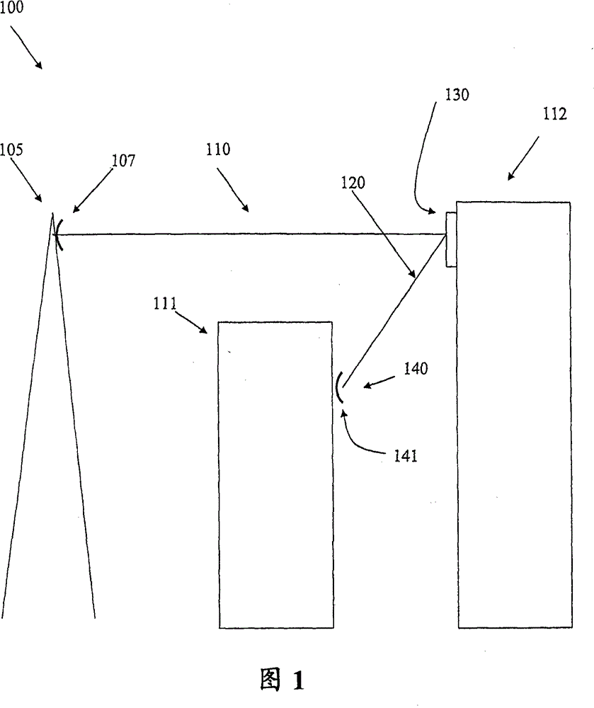
[0017] exist figure 1 In , a system 100 using the present invention is schematically illustrated. A radio base station (RBS) 105 is intended to cover a cell in a mobile telephone system. In a cell, there is an area that cannot be covered by the RBS 105, either due to the high density of users in that area such that the capacity of the RBS is insufficient, or because the line of sight (LOS) from the RBS to the area is obscured by, for example, tall buildings fact. exist figure 1 In , this area is represented as the RBS is obscured by buildings 111 .

[0018] Of course, these two factors may also appear in combination, and areas with a high density of users may be obscured by buildings or other obstacles.

[0019] Such as figure 1 As shown, there is an additional RBS 140 installed on the structure 111, such as a building, to assist the RBS 105 in covering the area in question. This additional RBS 140 may be a so-called "micro" or "pico" base station, ie a base station with...


PUM


Abstract

The present invention discloses a repeater antenna comprising a plurality of radiation elements arranged in a first electrically conducting layer or plane. The repeater antenna also comprises a ground plane spaced apart from the radiation elements by a layer of dielectric material, and the radiation elements are each given such an extension (L1, L2, L3) and such a distance (D12, D23) to neighboring radiation elements that an incident electromagnetic wave will reflect from the repeater antenna at an angle (alpha2) that by a predetermined amount will be greater or smaller than the incident angle (alpha2) of the electromagnetic wave. The repeater antenna is plane, and can be either curved or flat.

Description

technical field [0001] The present invention discloses a passive repeater antenna having a plurality of radiating elements arranged in a first layer or plane, which also includes a ground plane spaced from the radiating elements by a dielectric material. Background technique [0002] Operators of wireless systems, such as cellular telephone systems, often wish to increase system capacity in certain areas. In the case of cellular telephony, operators may wish to increase system capacity in certain areas of the cell. [0003] Increasing system capacity in a certain area of ​​a cell can be achieved by installing additional base stations to cover that area. Such an additional base station is generally a so-called "micro" or "pico" base station, ie having a reduced capacity compared to a normal base station, intended to enhance the capacity of a normal base station. Of course, a common base station can also be used to achieve the same effect. [0004] The simplest way of conne...

Claims


Application Information

Patent Timeline
Patent Type & Authority Patents(China)
IPC IPC(8): H04B7/155H01Q21/06
CPCH01Q3/46H01Q21/061H04B7/145
Inventor B·史文森A·斯特杰曼
Owner TELEFON AB LM ERICSSON (PUBL)
Why Eureka
Try Eureka