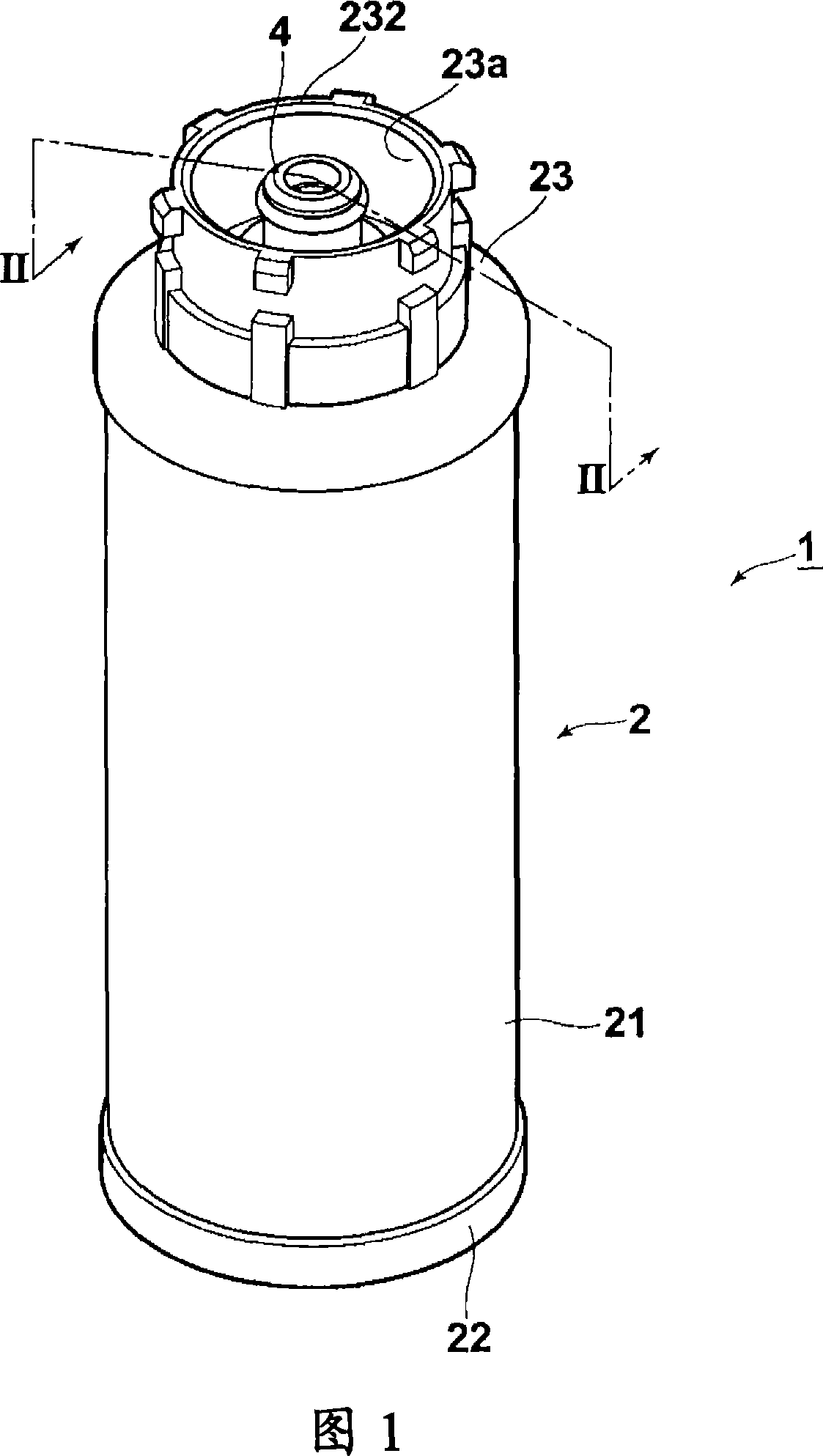
Fuel container for fuel cell
A fuel cell and fuel container technology, applied in the direction of fuel cells, fuel cell additives, solid electrolyte fuel cells, etc., can solve the problems of fuel storage room volume reduction, etc., to reduce the possibility, improve sliding, and defective rate Reduced effect
- Summary
- Abstract
- Description
- Claims
- Application Information
AI Technical Summary
Problems solved by technology
Method used
Image
Examples
Embodiment 1
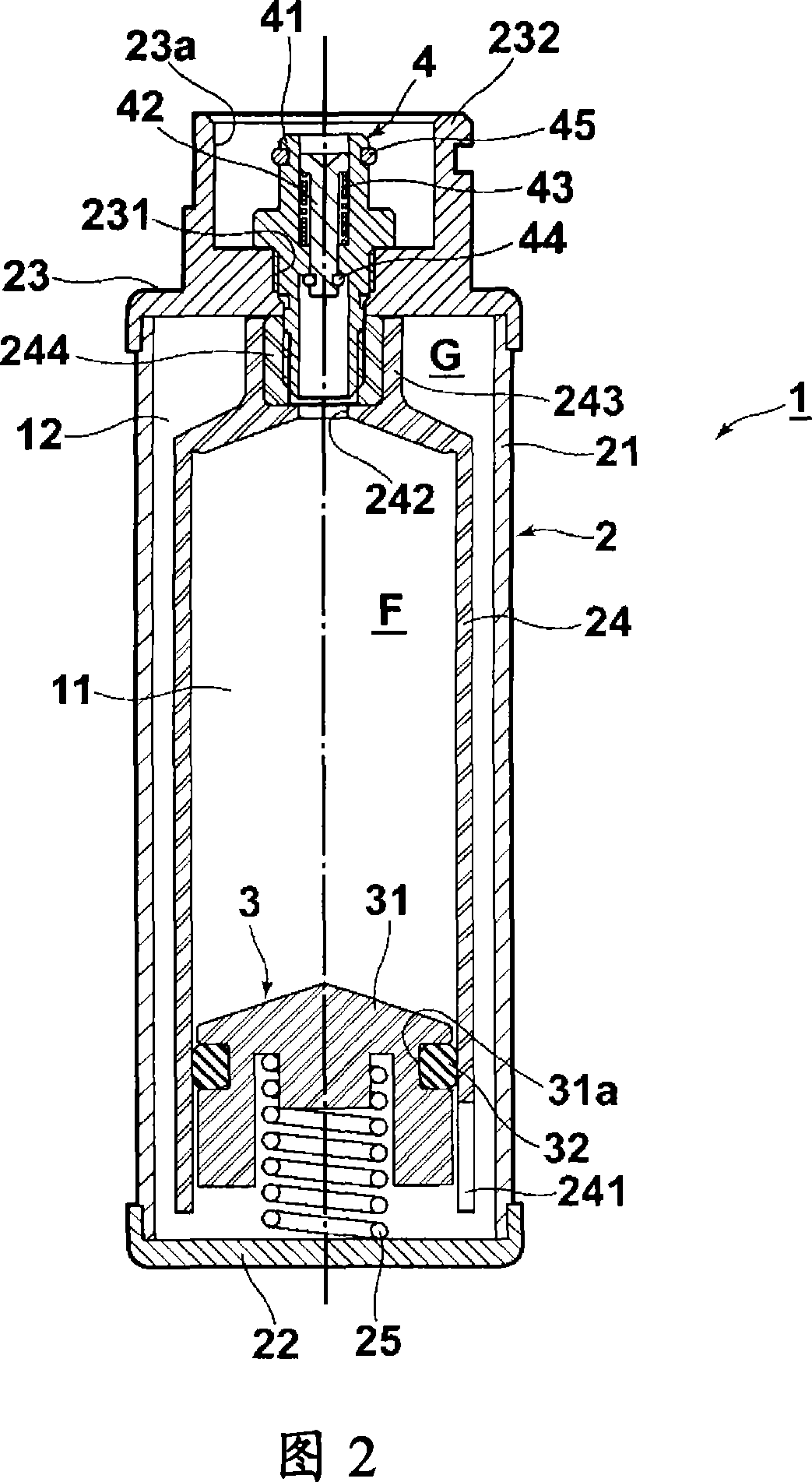
[0130] Repeated durability tests were performed using the inner container 24 , the partition member 3 (main body member 31 , O-ring 32 ) and the valve 4 described in the above embodiment. The inner container 24 and the main body member 31 were PP molded products, and the O-ring used had a structure in which a p-xylene dimer covering layer with a film thickness of 1 μm was formed on the outer surface of the EPDM molded product.
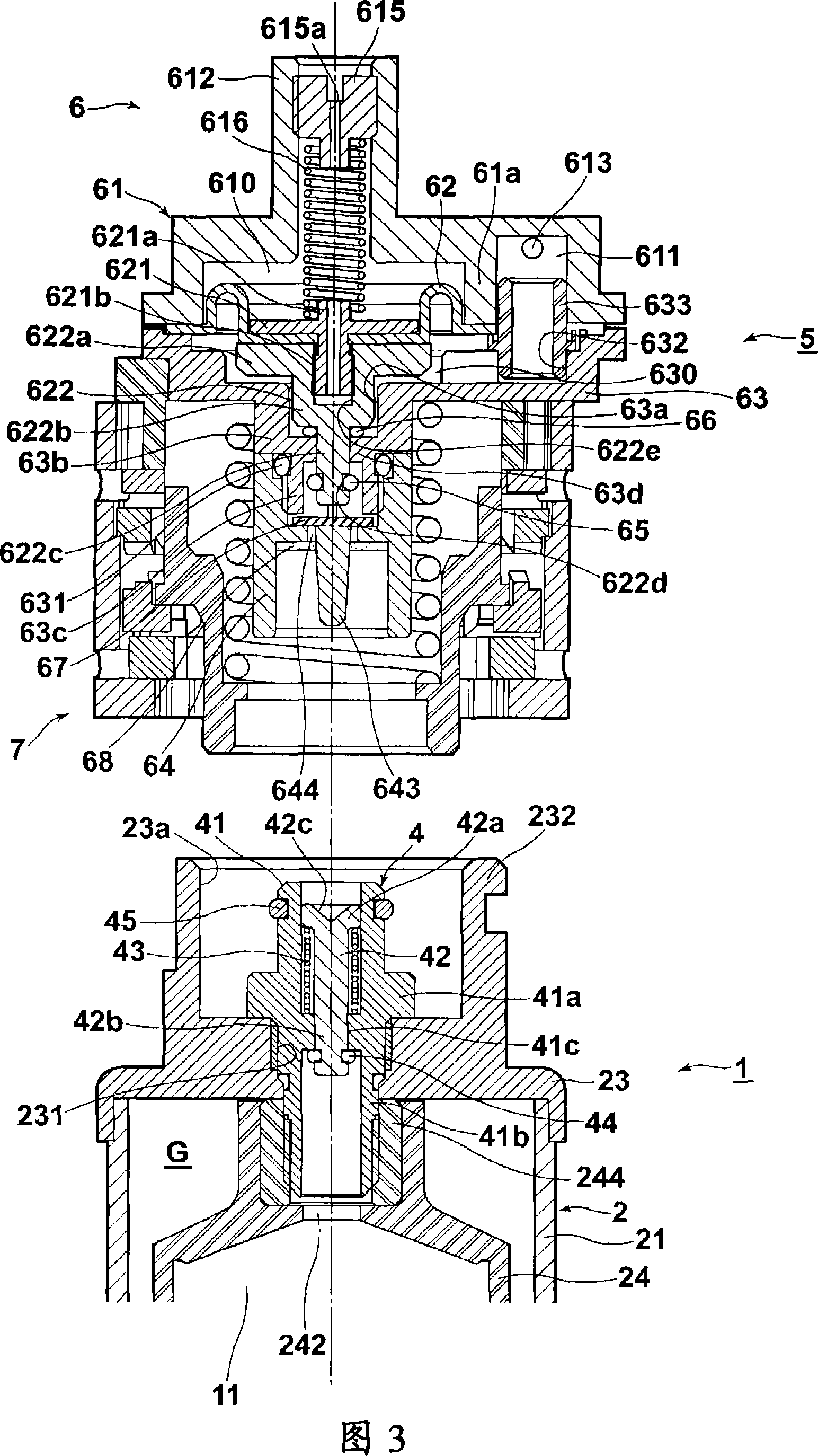
[0131] 1) First, in the state where the partition member 3 is located at the uppermost part of the inner container 24, a valve 4 is installed in the through hole 242, and 2 mL of pure methanol is filled into the inner container 24 through the valve 4, and then, the partition member 3 is placed downward. Push to expel the filled pure methanol through the valve. In order to remove the gas in the inner container 24, this operation is repeated twice.
[0132] 2) Next, 6 ml of a 30% by weight methanol aqueous solution containing 30% by weight of methanol a...
Embodiment 2
[0142] The aging test was carried out using the same apparatus as in Example 1 above. The test method was to perform the same operations as (1) to (2) of the above-mentioned Example 1, and then place the above-mentioned device in an environment of 65° C., and perform the operation of (3) after a predetermined time elapsed.
[0143] 5) after the measured value, install valve 4 rapidly, fill described 30% by weight aqueous methanol solution in inner container 24 through valve 4, return to the state after (2) action of above-mentioned embodiment 1, then, put above-mentioned device again Place it in an environment of 65°C, and carry out the operation of (3) after the predetermined time has elapsed. Then, the operation of (5) above was repeated, and the change in the sliding friction force was measured when the standing time elapsed. In this test, the standing time refers to the cumulative time of standing in an environment of 65° C., and does not include the time required for mea...
Embodiment 3
[0151] The seal failure test of the O-ring was performed using the same apparatus as in Example 1 above. The test method is to carry out the same operation as (1)-(2) of the above-mentioned embodiment 1, and then, make the filled 30% by weight methanol aqueous solution flow out from the container for 30 minutes through the valve 4 at an outflow rate of 6mL / 60-120min . Then, the number of containers in which gas was mixed due to poor sealing of the O-ring was counted.
PUM
| Property | Measurement | Unit |
|---|---|---|
| thickness | aaaaa | aaaaa |
| thickness | aaaaa | aaaaa |
| thickness | aaaaa | aaaaa |
Abstract
Description
Claims
Application Information
 - R&D
- Intellectual Property
- Life Sciences
- Materials
- Tech Scout
- Unparalleled Data Quality
- Higher Quality Content
- 60% Fewer Hallucinations
Browse by: Latest US Patents, China's latest patents, Technical Efficacy Thesaurus, Application Domain, Technology Topic, Popular Technical Reports.
© 2025 PatSnap. All rights reserved.Legal|Privacy policy|Modern Slavery Act Transparency Statement|Sitemap|About US| Contact US: help@patsnap.com


