Method for measuring Cube-Prism non-orthogonality angle and scale factor correct value

A scaling, non-orthogonal technology, applied in the field of semiconductor manufacturing, can solve problems such as limitations in the use of lithography machines, and achieve the effect of simple marking design

Active Publication Date: 2008-07-09
SHANGHAI MICRO ELECTRONICS EQUIP (GRP) CO LTD
View PDF0 Cites 13 Cited by
  • Summary
  • Abstract
  • Description
  • Claims
  • Application Information

AI Technical Summary

Problems solved by technology

[0004] The present invention provides a method for measuring the non-orthogonal angle of the square mirror and the correction value of the scaling factor in order to solve the shortcomings of the existing measurement method that has limitations in the use of photolithography machines

Method used


Image

  • Method for measuring Cube-Prism non-orthogonality angle and scale factor correct value
  • Method for measuring Cube-Prism non-orthogonality angle and scale factor correct value

Examples


Embodiment Construction

[0026] A method for measuring the non-orthogonal angle of a square mirror and the correction value of the scaling factor of the present invention will be described in detail below in conjunction with specific embodiments.

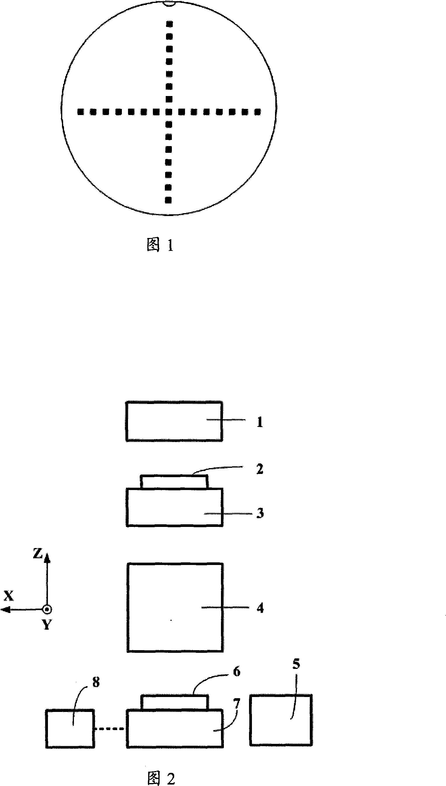
[0027] The lithography machine system for exposure and alignment measurement used in the present invention is shown in Figure 2, including: an illumination system 1, a mask table 3 carrying a mask 2, an optical system 4 for mask imaging, and a silicon The workpiece table 7 of the sheet 6, the alignment system 5 for off-axis alignment, the X-direction interferometer 8 and the Y-direction interferometer 9 for monitoring the movement position of the workpiece table.

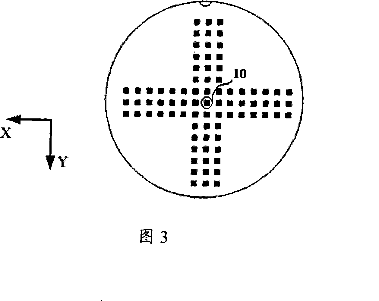
[0028] In the present invention, two alignment marks on the mask are used for exposure, mark A and mark B, mark A and mark B are off-axis alignment marks of the same type, which measure the square mirror non-orthogonality angle and the scaling factor correction value The specific steps are:

[0...


PUM


Abstract

A method for measuring corrected values of non-rothogonality angles and scaling factors of a square mirror comprises the following steps: placing and exposing a marking image (A) on a mask onto a gummed blank silicon wafer via a photoetching system according to a designated graph, and taking off the wafer when exposure is completed; putting up the wafer after rotating the silicon wafer by a certain angle, placing and exposing a marking image (B) on the mask onto the silicon wafer according to the same graph, wherein compared to the first layer, the exposure marking position is deviant; developing again when the exposure is completed; putting up the wafer again without rotating the silicon wafer, and reading all the marking positions after aligning the marks on the silicon wafer via an off-axis alignment system of a photographic machine; and calculating the non-rothogonality angles and the scaling factors of a coordinate system of a working piece table according to the measured marking positions. The measurement method is an absolute measurement method, and can be applied in different photoetching systems.

Description

technical field [0001] The invention relates to the field of semiconductor manufacturing, in particular to a method for measuring the non-orthogonal angle of a square mirror and the correction value of a scaling factor. Background technique [0002] Because there is a certain mechanical deviation when the X square mirror and Y square mirror of the workpiece table are installed, the X square mirror and Y square mirror in the actual lithography machine system are not absolutely vertical, which leads to the establishment of the workpiece table coordinate system (coordinate system y axis Parallel to the X square mirror) there is non-orthogonality. When the workpiece table scans and exposes along the X and Y axes, the resulting graphics will appear distorted. In addition, due to the mismatch between the X and Y direction interferometers of the workpiece table, the scaling ratio between the X-axis and Y-axis coordinates will be different. [0003] The commonly used method to det...

Claims


Application Information

Patent Timeline
Patent Type & Authority Applications(China)
IPC IPC(8): G03F7/20G03F9/00
Inventor 李煜芝
Owner SHANGHAI MICRO ELECTRONICS EQUIP (GRP) CO LTD
Why Eureka
Try Eureka