Battery state monitoring circuit and battery device

A technology for monitoring the state of circuits and batteries, which is applied to battery circuit devices, circuit devices, battery over-discharge protection, etc., and can solve problems such as power-off status and battery device failure to operate normally

Inactive Publication Date: 2008-07-02
SEIKO INSTR INC
View PDF1 Cites 12 Cited by
  • Summary
  • Abstract
  • Description
  • Claims
  • Application Information

AI Technical Summary

Problems solved by technology

In the future, even if the charger 301 is correctly connected, it may still be in a state of power failure, and the battery device cannot operate normally.

Method used


Image

  • Battery state monitoring circuit and battery device

Examples


Embodiment Construction

[0019] Hereinafter, embodiments of the present invention will be described with reference to the drawings.

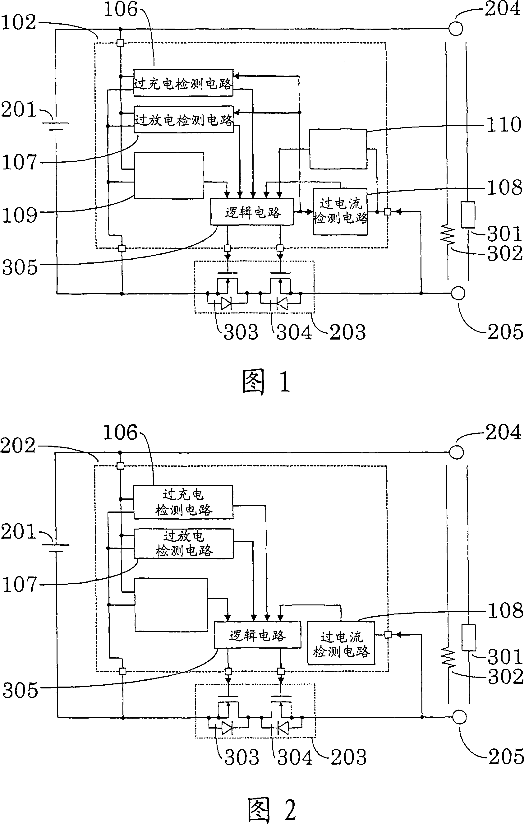
[0020] FIG. 1 is a circuit block diagram of a battery device.

[0021] The battery state monitoring circuit 102 is composed of an overcharge detection circuit 106 , an overdischarge detection circuit 107 , an overcurrent detection circuit 108 , a second power interruption prevention circuit 109 , a first power interruption prevention circuit 110 and a logic circuit 305 .

[0022] The battery state monitoring circuit 102 connects a voltage detection terminal for monitoring the positive voltage and the negative voltage of the battery 201 to the battery 201 which can be charged and discharged, and operates the battery 201 as a power source.

[0023] In the battery state monitoring circuit 102, the voltage of the battery 201 is lower than the upper limit voltage that can be charged and is higher than the lower limit voltage that can be discharged. When the current is prede...


PUM


Abstract

The present invention provides a circuit for monitoring cell state and a cell device which can still work when a charger (301) is connected correctly after the charger is connected to the positive-negative phase of the cell device incorrectly. When the charger (301) is connected to the positive and negative electrodes incorrectly, and the charger (301) is connected correctly later on, to prevent a logic circuit (305) from outputting powerdown signal to each circuit by means of a powerdown circuit (110), thus the cell device can motion normally without locating powerdown state.

Description

technical field [0001] The present invention relates to a battery state monitoring circuit for monitoring the battery state of a battery device connected to a charger or a load, and a battery device equipped with the circuit. Background technique [0002] As a conventional battery device, a battery device shown in FIG. 2 is known. FIG. 2 is a circuit block diagram of a conventional battery state monitoring circuit and a battery device. [0003] The battery state monitoring circuit 202 is composed of an overcharge detection circuit 106 , an overdischarge detection circuit 107 , an overcurrent detection circuit 108 , and a logic circuit 305 . [0004] In the battery state monitoring circuit 202, when a predetermined condition is satisfied, the logic circuit 305 outputs a high-level signal to turn on the FET304 and the FET303 in the switch circuit 203 (this state is called a normal state). [0005] And, the charger 301 is connected between the external terminal (+V0) 204 and ...

Claims


Application Information

Patent Timeline
Patent Type & Authority Applications(China)
IPC IPC(8): H02J7/00
CPCH02J2007/0039H02J7/0034H02J2007/004H02J2007/0037H02J7/00302H02J7/00304H02J7/00306G01R31/36
Inventor 桜井敦司佐野和亮小池智幸
Owner SEIKO INSTR INC
Why Eureka
Try Eureka