Multipoint ignition engine
An engine and multi-point technology, applied in the direction of engine ignition, engine components, machines/engines, etc., can solve problems such as fuel waste discharge, increase in the amount of HC and CO, and deterioration of emission performance, so as to improve output and fuel efficiency. The effect of suppressing loss
- Summary
- Abstract
- Description
- Claims
- Application Information
AI Technical Summary
Problems solved by technology
Method used
Image
Examples
no. 1 approach
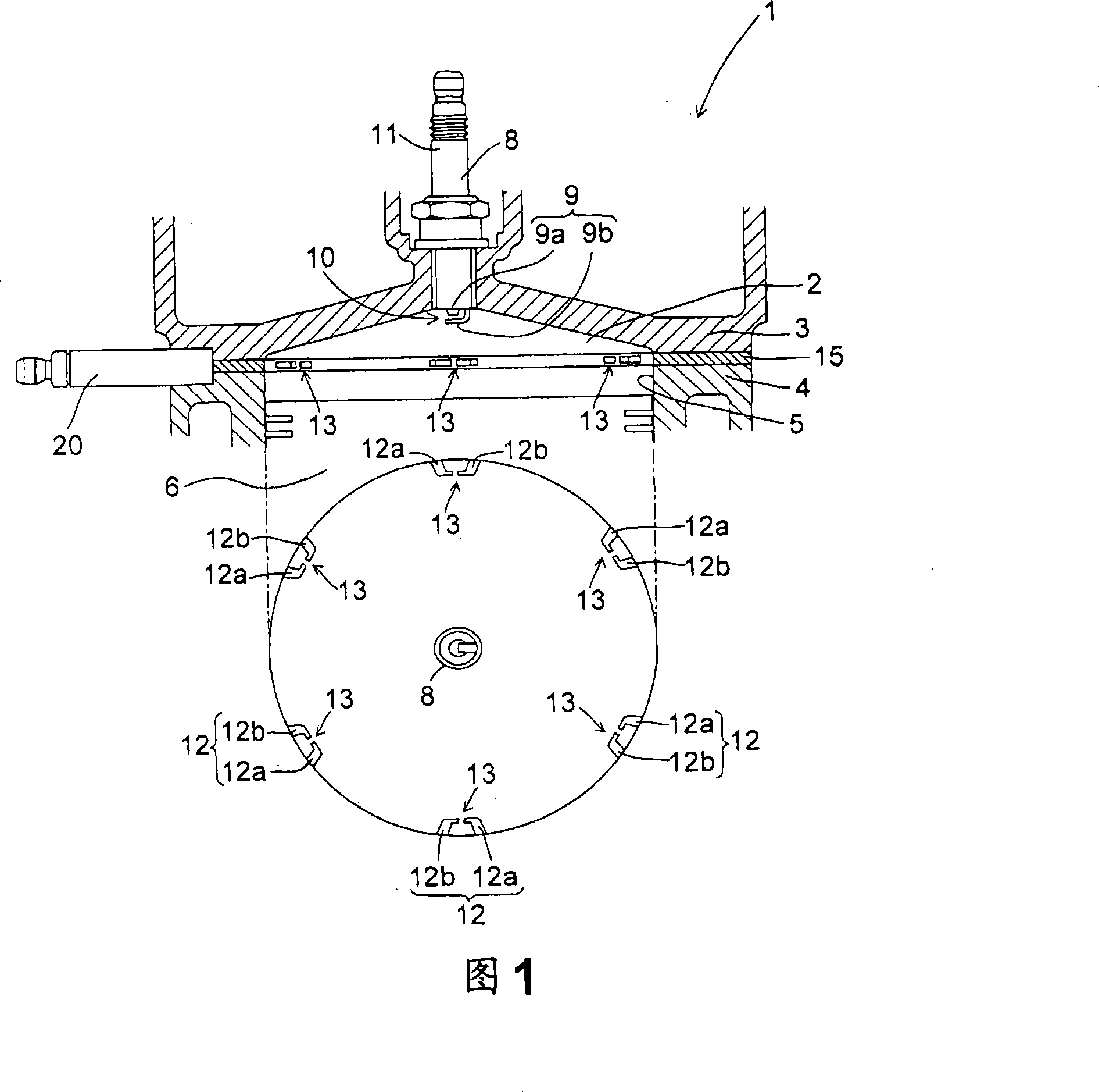
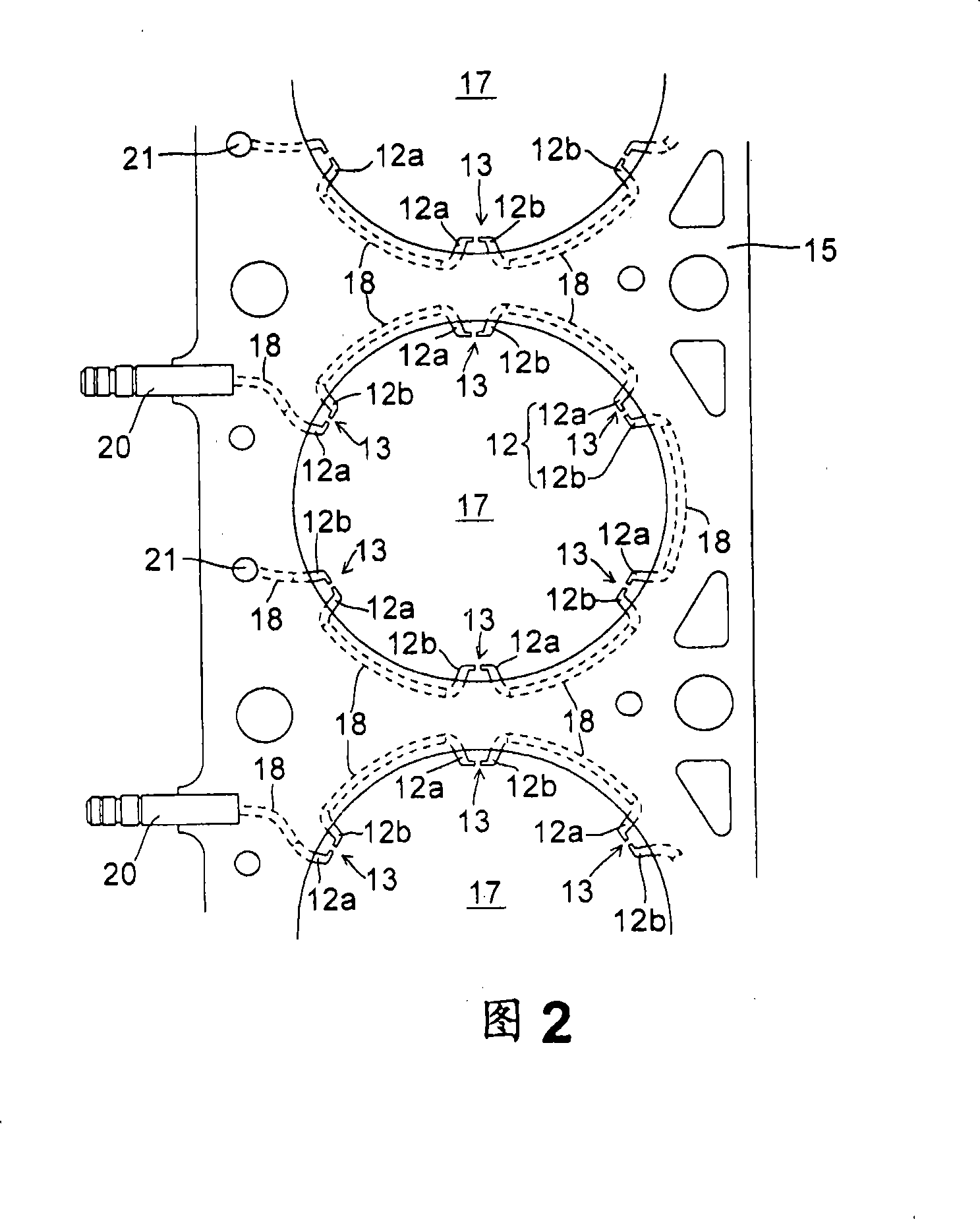
[0038] FIG. 1 shows a schematic construction of a multi-point ignition engine 1 according to the invention.
[0039] In the present embodiment, the engine 1 is a premixed engine in which the fuel injected through an injector connected to the intake port not shown in the figure is uniformly mixed with the air, and when the air-fuel mixture is introduced into the combustion chamber 2, the The spark ignites and burns. In order to obtain the desired air-fuel ratio, the amount of intake air and the amount of fuel injected by the injectors are adjusted. As will be described below, the engine 1 may be a direct injection engine. To improve fuel efficiency, the air-fuel ratio of the air-fuel mixture is set higher than the stoichiometric air-fuel ratio (for example, an excess air factor of about 2), but ensures that the output of the engine 1, the air-fuel mixture The air-fuel ratio is set to be equal to or less than (richer) the air-fuel ratio depending on the operating region or sto...
no. 2 approach
[0079] In order to further improve the output and fuel efficiency of the above-mentioned multi-point ignition engine 1 , the compression ratio of the engine 1 can be increased by reducing the thickness of the cylinder head gasket 15 . As the compression ratio increases, thermal efficiency increases, resulting in improved output and fuel efficiency. However, when the thickness of the cylinder head gasket 15 is reduced, the distance between the peripheral spark gap 13 and components such as the cylinder head 3 is reduced, resulting in an increased possibility of leakage. Leakage often occurs especially when the thickness of the cylinder head gasket 15 is set to 6 mm or less. This also happens when the capacitance of the ignition coil increases.
[0080] In the second embodiment, as shown in FIGS. 7 and 8 , leak-proof recesses 23 , 24 are formed by forming leak-proof recesses 23 , 24 at positions corresponding to positions in the circumferential direction of the upper peripheral...
no. 3 approach
[0084] In order to suppress leakage from the peripheral spark gap 13 into the cylinder head 3 and the like, the third embodiment differs from the first embodiment in the structure of the peripheral electrode pair 12 . All other structures are the same as those of the first embodiment.
[0085] FIG. 11 shows the structure of the peripheral electrode pair 12 according to the third embodiment. The portion of the peripheral electrode pair 12 exposed inside the combustion chamber 2 has the form of a linear rod without a curved portion in the middle. Further, it is formed by making the tip end surface of one of the electrodes (ground electrode 12b) constituting the peripheral electrode pair 12 face the tip end-side sideface of the other electrode (conductive electrode 12a) with a gap therebetween. Peripheral spark gap 13. The angle formed by the exposed parts of the electrodes 12a, 12b is substantially 90°.
[0086] With this structure, since there is no bent portion in the middl...
PUM
 Abstract
Description
Claims
Application Information
 - R&D
- Intellectual Property
- Life Sciences
- Materials
- Tech Scout
- Unparalleled Data Quality
- Higher Quality Content
- 60% Fewer Hallucinations
Browse by: Latest US Patents, China's latest patents, Technical Efficacy Thesaurus, Application Domain, Technology Topic, Popular Technical Reports.
© 2025 PatSnap. All rights reserved.Legal|Privacy policy|Modern Slavery Act Transparency Statement|Sitemap|About US| Contact US: help@patsnap.com


