
Panel detection device

A panel detection and panel technology, which is applied in nonlinear optics, instruments, optics, etc., can solve the problems of large space occupation, high cost, and complex structure arrangement of the positioning mechanism, and achieve the effect of simplifying mechanical design and reducing equipment cost

Inactive Publication Date: 2008-07-02
FOXSEMICON INTEGRATED TECHNOLOGY (SHANGHAI) INC +1
View PDF0 Cites 4 Cited by
  • Summary
  • Abstract
  • Description
  • Claims
  • Application Information

AI Technical Summary

Problems solved by technology

[0005] However, the panel detection device with the above-mentioned dual-port design requires a positioning mechanism for the panel code reading module and the panel electrode cleaning module respectively, so that the code reading and electrode cleaning take a long time, resulting in the overall The detection process takes a long time, and the two positioning mechanisms take up a lot of space, and the structure arrangement is also complicated, which makes the cost of the panel detection device with this dual-port design higher

Method used


Image

  • Panel detection device
  • Panel detection device
  • Panel detection device

Examples


Embodiment Construction

[0015] The present invention will be further described in detail below in conjunction with the accompanying drawings.

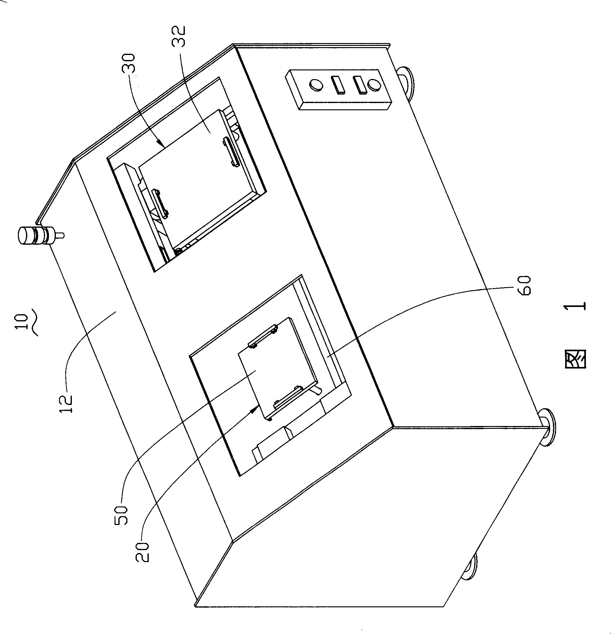
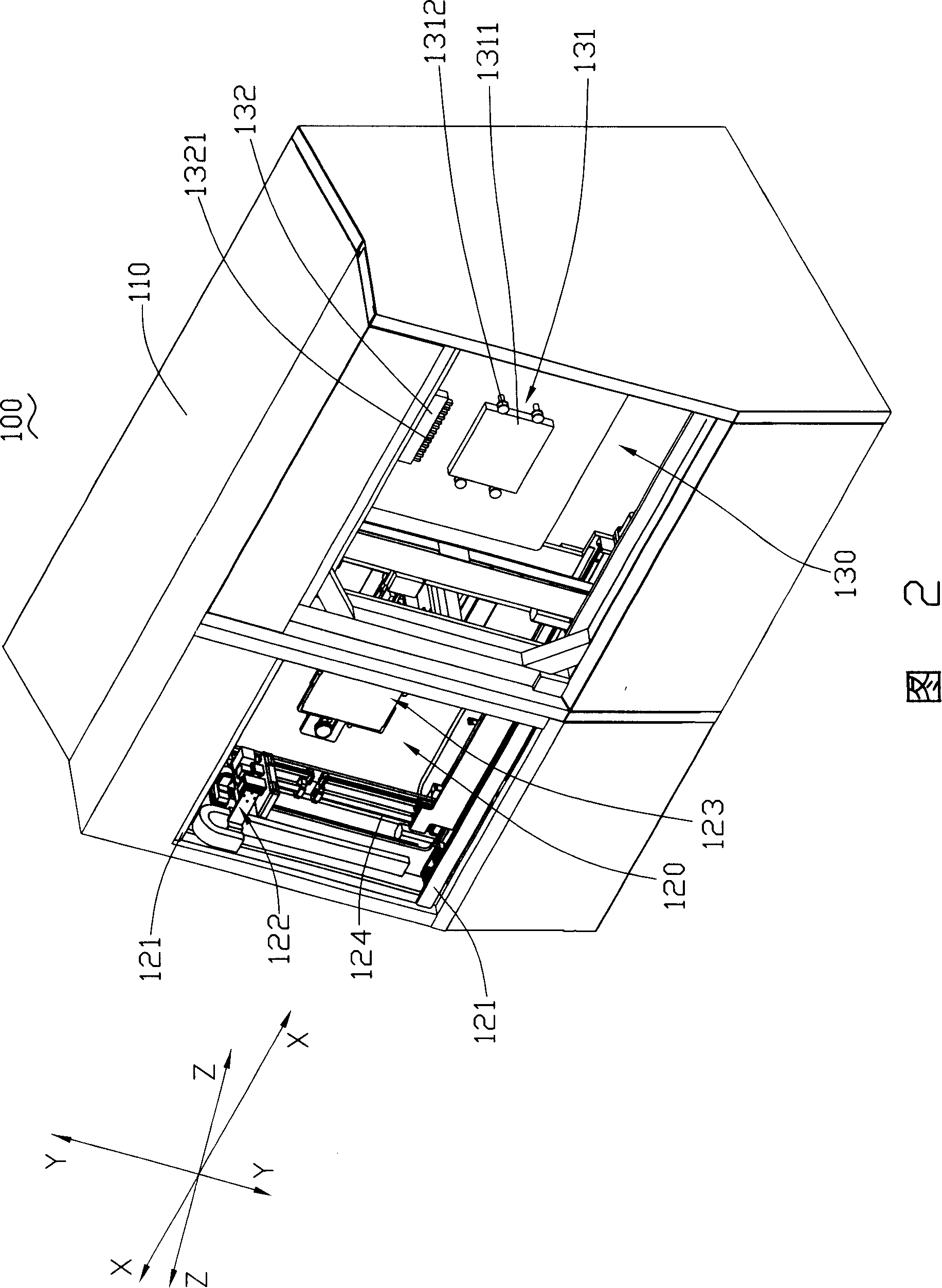
[0016] Please refer to FIG. 2 , the panel inspection device 100 provided by the embodiment of the present invention includes a body 110 and a pick-and-place part 120 and a detection part 130 arranged on the body 110 . The pick-and-place unit 120 is provided with a positioning substrate 121 , a reading and cleaning module 122 , a pre-clamping mechanism 123 , and a main conveying mechanism 124 . The detection unit 130 is provided with a detection table 131 and a detection mechanism 132 .

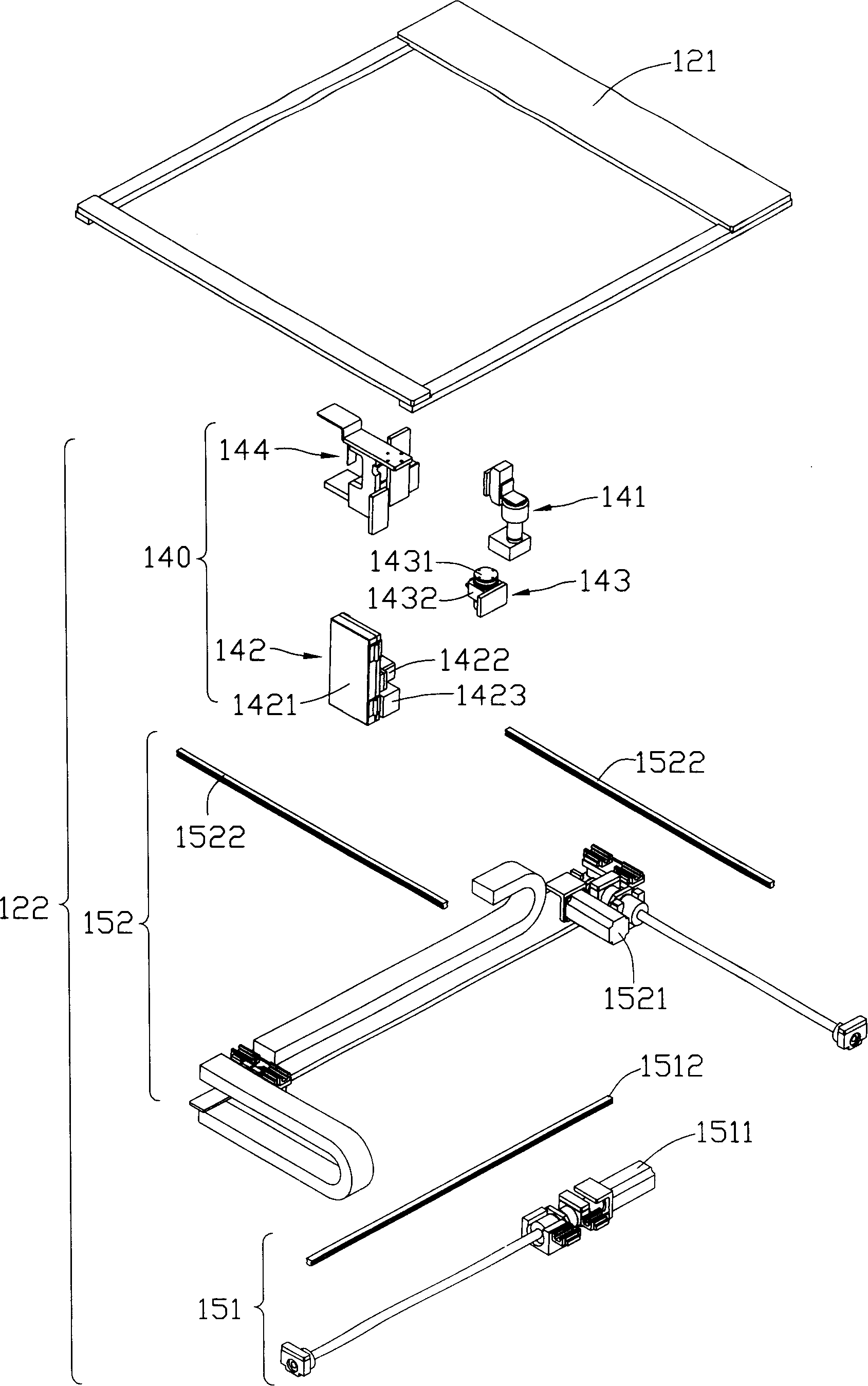
[0017] See also image 3 , FIG. 4 and FIG. 5, the reading cleaning module 122 includes a reading cleaning unit 140, a first transmission mechanism 151 for driving the reading cleaning unit 140 to move along the Y-axis direction, and a first transmission mechanism 151 for driving the first The transport mechanism 151 and the second transport mechanism 152 that the reading and...


PUM


Abstract

The invention relates to a panel detection device used in the manufacture field of flat-panel displays and includes a part for taking up and down and a detection part, wherein, the part for taking up and down is arranged with a reading and cleaning module which comprises a reading and cleaning unit, the reading and cleaning unit comprises a code reading mechanism and a cleaning mechanism, the code reading mechanism is used to read codes on a panel to be detected, and the cleaning mechanism is used to clean metal electrode on the panel to be detected; a first transport mechanism which is used to drive the reading and cleaning unit to move along a first direction; and a second transport mechanism which is used to drive the reading and cleaning unit and the first transport mechanism to move along a second direction which is vertical to the first direction.

Description

technical field [0001] The invention relates to a panel detection device used in the field of flat panel display manufacture. Background technique [0002] Usually, after the thin film transistor liquid crystal display panel assembly (TFT-LCD cell) process is completed, it is necessary to use a panel inspection device (also called a lighting tester) to inspect the image display status and whether there is any defect of the bonded liquid crystal display panel. The basic steps to perform this test are: accurately position the liquid crystal display panel to be tested, and set a backlight source (such as a light box) to provide an illumination source for the liquid crystal display panel to be tested; use a fine probe set (Probe Unit) Contact each signal transmission point on the liquid crystal display panel to be tested; then transmit various display signals to be tested to the liquid crystal display panel, this working process is called lighting or lighting (Light-On); Inspec...

Claims


Application Information

Patent Timeline
Patent Type & Authority Applications(China)
IPC IPC(8): G02F1/13
Inventor 黄俊凯蔡升富伍家贤邱义君
Owner FOXSEMICON INTEGRATED TECHNOLOGY (SHANGHAI) INC
Learn More