
Electronic compass system

An electronic compass and circuit technology, applied in the direction of the compass, the use of electrical devices, the use of electromagnetic means, etc., can solve the problem of not using the Z-axis sensor to determine the direction and so on

Inactive Publication Date: 2010-12-08
GENTEX CORP
View PDF46 Cites 0 Cited by
  • Summary
  • Abstract
  • Description
  • Claims
  • Application Information

AI Technical Summary

Problems solved by technology

However, this compass system does not utilize the Z-axis sensor for orientation or to identify the center of the circle used for calibration

Method used


Image

  • Electronic compass system
  • Electronic compass system
  • Electronic compass system

Examples


no. 1 approach 1

[0301] Like the first embodiment, the second embodiment derives the vehicle orientation using an approximate geometric pattern that is the best-fit pattern determined through several iterations. When data is acquired from a magnetic sensor, the data is first processed to determine if the data point is stable. The stable data points are then processed to generate a list of reference data points maintained in the reference list, with the most recent reference data point at the top. When older reference points are revisited, they move to the top of the list. Thus stale points are discarded from the bottom of the stack as explained further below. The reference points are used to determine the best fit geometric approximation pattern and thus the calibration points used to determine the orientation of the vehicle. The approximate geometric pattern is calculated in several iterations based on the X and Y values ​​of the reference point, the assumed radius R, and the elliptic const...


PUM


Abstract

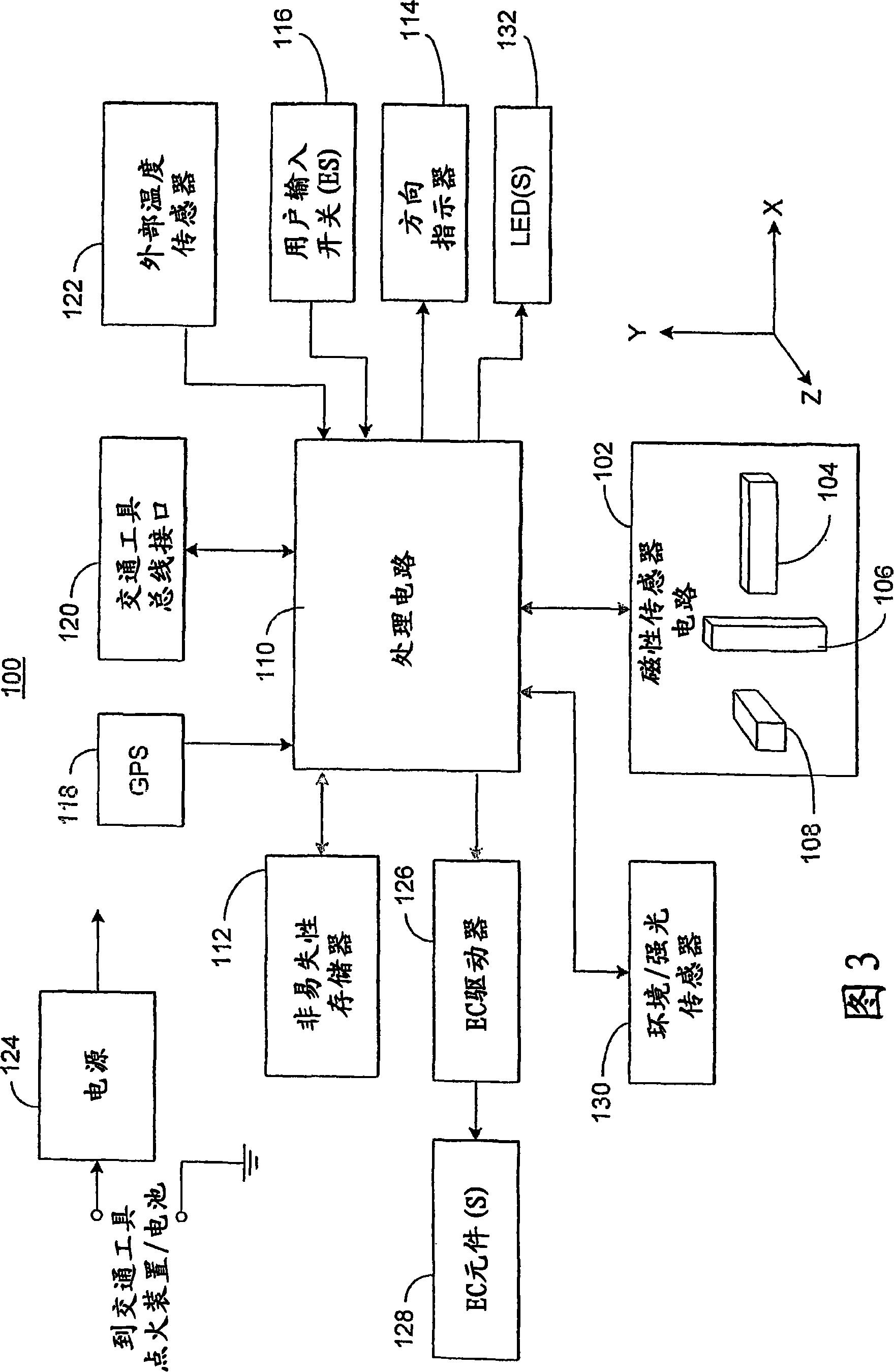
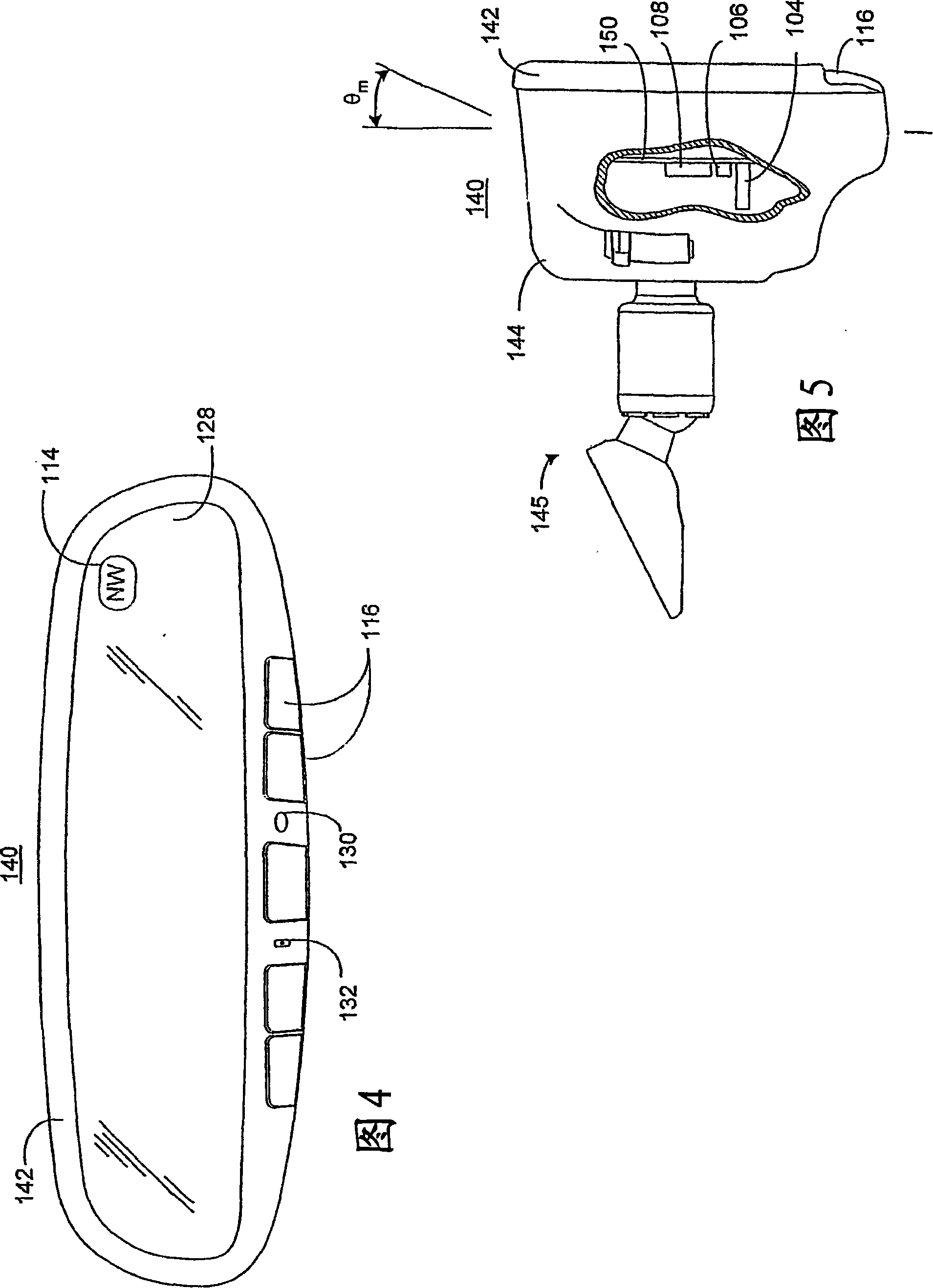
An electronic compass system includes a magnetic sensor circuit having at least two sensing elements for sensing perpendicular components of the Earth's magnetic field vector. A processing circuit is coupled to the sensor circuit to filter, process, and compute a heading. The processing circuit may determine whether too much noise is present in the output signals received from said magnetic sensor circuit as a function of the relative strength of the Earth's magnetic field vector. The magnetic sensor circuit may include three magnetic field sensing elements contained in a common integrated package having a plurality of leads extending therefrom for mounting to a circuit board. The sensing elements need not be perpendicular to each other or parallel or perpendicular with the circuit board.The electronic compass system is particularly well suited for implementation in a vehicle rearview mirror assembly.

Description

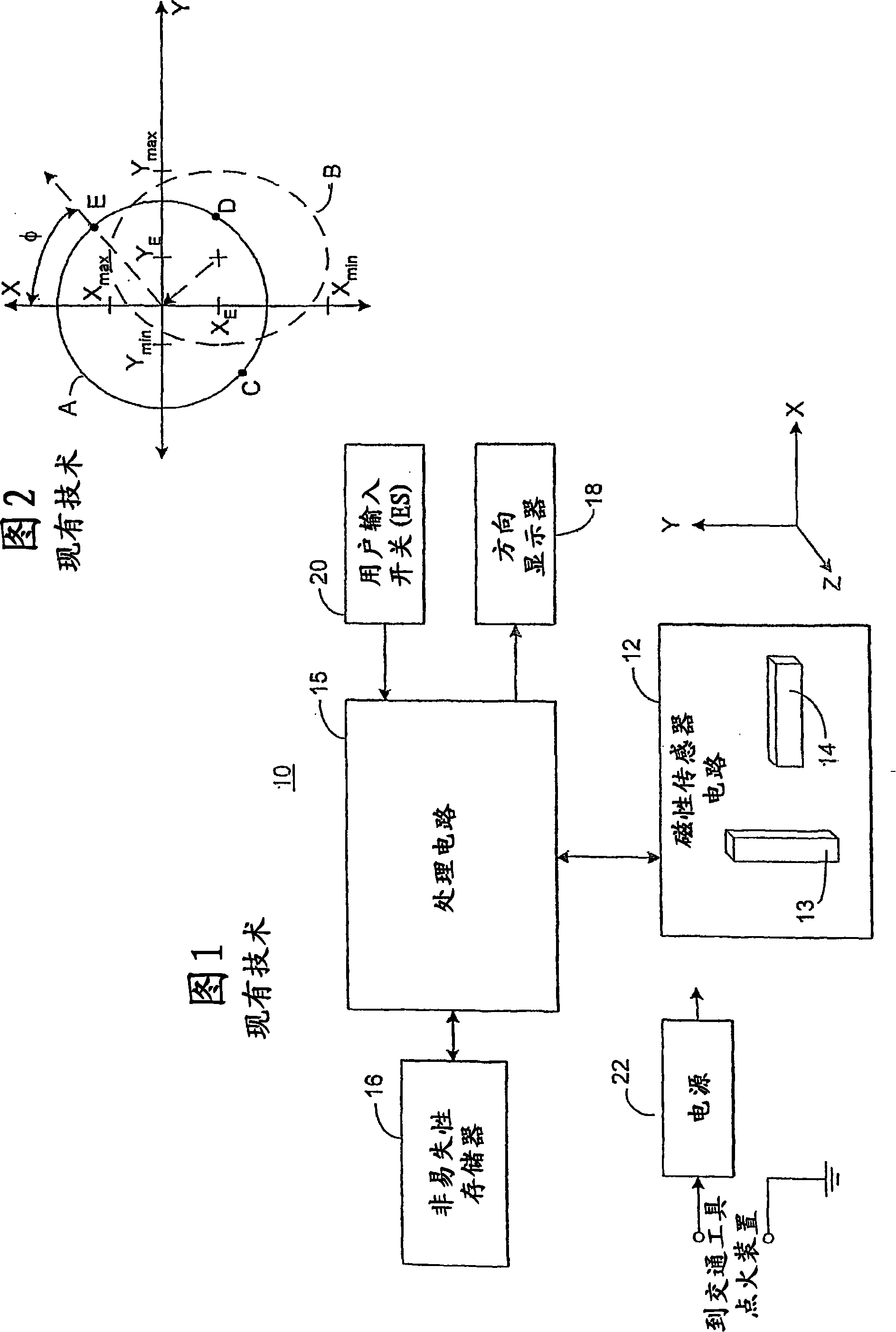
[0001] Cross References to Related Applications [0002] This application is a continuation-in-part of U.S. Patent Application No. 10 / 210,910, filed August 2, 2002, which claims 35 U.S.C. § 119(e ) priority interest. [0003] This application also claims the benefit of priority under 35 U.S.C. §119(e) of US Provisional Patent Application No. 60 / 449,828, filed February 24,2003. [0004] The entire disclosure of each of the above applications is hereby incorporated by reference. technical field [0005] The present invention relates generally to an electronic compass for a vehicle, and more particularly to an electronic compass with improved data filtering and / or direction determination. Background technique [0006] Electronic compasses have become increasingly popular as accessories in automobiles. The general structure of a typical electronic compass circuit 10 is shown in FIG. 1 . In particular, a typical electronic compass circuit includes a magnetic sensing circuit ...

Claims


Application Information

Patent Timeline
Patent Type & Authority Patents(China)
IPC IPC(8): G01B7/30G01R33/06G01C17/28G01C17/30G01C17/32G01C17/38
CPCG01C17/38G01C17/28G01C17/30
Inventor 哈罗尔德·C·奥克斯乔恩·H·贝克特尔马克·D·布格诺
Owner GENTEX CORP
Learn More