
Driving apparatus and image pickup apparatus

A technology of driving device and camera device, applied in installation, generator/motor, piezoelectric effect/electrostrictive or magnetostrictive motor, etc., can solve the problems of bulkiness, violation of miniaturization, complex mechanism, etc., and achieve high efficiency The effect of high and high driving force

Inactive Publication Date: 2008-06-25
OLYMPUS CORP
View PDF2 Cites 15 Cited by
  • Summary
  • Abstract
  • Description
  • Claims
  • Application Information

AI Technical Summary

Problems solved by technology

In such a structure, a separate route is required for the driving force transmission mechanism on the lens frame side, the guide mechanism for the lens frame side, etc., and there is a problem that the mechanism becomes complicated, large and heavy.
Based on this point, the rigidity of the moving object itself such as the lens frame is increased so that it can be directly driven by the elliptical vibration of the vibrator. When the driving force is transmitted, inherent vibrations and other disadvantages occur, and it is necessary to increase the size and weight more than necessary, which violates the requirement for miniaturization.

Method used


Image

  • Driving apparatus and image pickup apparatus
  • Driving apparatus and image pickup apparatus
  • Driving apparatus and image pickup apparatus

Examples


Embodiment Construction

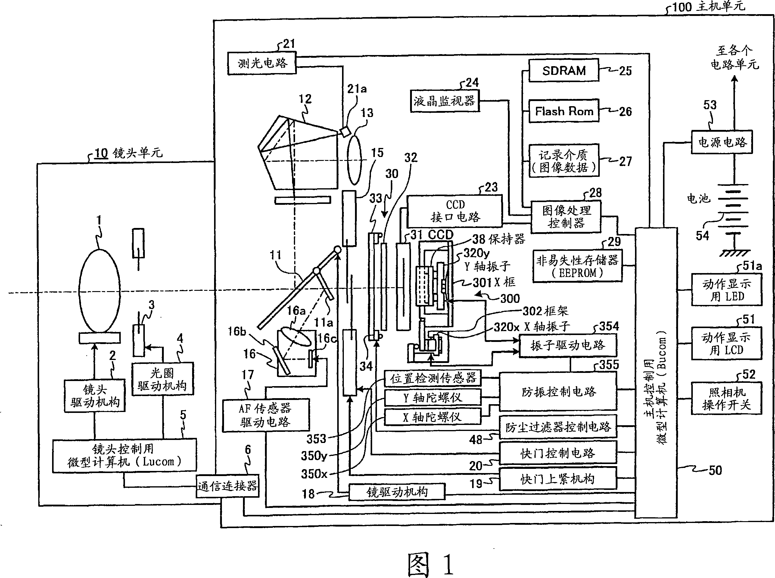
[0028] Hereinafter, the best mode for implementing the driving device and the imaging device according to the present invention will be described with reference to the drawings. The imaging device of this embodiment is equipped with a driving device for performing hand shake correction of an imaging unit including an imaging element that obtains an image signal by photoelectric conversion. An application example of an electronic camera (digital camera) will be described. In addition, the present invention is not limited to the embodiments, and various modifications can be made as long as they do not depart from the gist of the present invention.

[0029] First, a configuration example of a camera system according to the present embodiment will be described with reference to FIG. 1 . FIG. 1 is a block diagram schematically showing the configuration of main electrical systems of a camera according to this embodiment. The camera of the present embodiment is systematically compo...


PUM


Abstract

The present invention provides a driving apparatus and an image pickup apparatus, the driving apparatus has miniature drive force and high efficiency. An X-axis transducer (320x) generating elliptical vibration is used as driving source, alternatively on side of a mobile body (311x), according to separation construction of X frame (301) forming desired size as mobile object and a sliding body (330x) small than the X frame (301), both of them are fixed and integrated, by a slicing plate (332x) and a bearing (331x) on the small sliding body (330x), driving force transmission function and mobile direction guide function are collected, a large X frame (301) and a sliding body (330x) are integrated to only carry out follow movement, thus high efficiency of driving force transmission can be carried out only by forming rigidity on the sliding body (330x) side, alternatively, the high rigidity like on the sliding body (330x) side is unnecessary to the X frame (301) side, form of desired size by adopting light quality material is satisfied, and special guide mechanism for restraining the mobile direction of the X frame (301) is unnecessary.

Description

technical field [0001] The present invention relates to a driving device for driving a moving body to move in a predetermined direction by elliptical vibration of a vibrator, and an imaging device such as a digital camera for performing shake correction by the driving device. Background technique [0002] Conventionally, as an imaging device having a shake correction function, there is a camera, for example. As a camera-shake correction function, there is known a hand-shake correction function that uses a shake detection unit such as an angular velocity sensor to detect shake vibrations in the direction of the camera's vertical tilt (ツツチ) and camera shake vibrations in the direction of the camera's tilt (ヨ一), According to the detected shaking signal, in the direction of canceling the shaking, a part of the imaging optical system or the imaging element is moved independently in the horizontal direction and the vertical direction in the plane perpendicular to the imaging optic...

Claims


Application Information

Patent Timeline
IPC IPC(8): H02N2/02G02B7/04
Inventor 川合澄夫
Owner OLYMPUS CORP
Learn More