
Auto-tracking sun device

An automatic tracking and sun technology, which is applied in the field of solar energy utilization, can solve the problems of no comprehensive detailed description, no description of the hinged connecting rod of the main shaft, and the inability of the main shaft to move up and down.

Inactive Publication Date: 2008-06-25
陈红专
View PDF6 Cites 21 Cited by
  • Summary
  • Abstract
  • Description
  • Claims
  • Application Information

AI Technical Summary

Problems solved by technology

The Chinese patent with the application number 03262564.2 discloses a screw-type declination automatic tracker. The main points of the program are: the lever moves the rocker so as to turn the base gear of the two-way single transmission, thereby driving the nut gear to connect and drive the non-rotating The screw rod moves up and down, thereby driving the light-absorbing body to rotate; the idea of ​​changing seasons in winter and summer is very novel, but 1. If the screw rod does not rotate, the nut screwed with it must rotate, and its return spring is connected to the declination bracket. How does the nut rotate? 2. It is required to calculate and adjust the dialing angle of the crank handle very accurately during the installation of winter and summer steering, and sometimes it is not completely reliable; 3. How to change the direction of the two-way single transmission lever in winter and summer, there is no comprehensive detailed description
The Chinese patent application number 200520079018.1 discloses a kind of adjustable reflector of horizontally arranged solar collector tubes, the main point of which is: the main shaft connects and drives multiple reflectors in the same row through connecting rods; it saves many trackers, but Obviously, the problem of the thermal expansion and contraction of the main shaft under direct sunlight will affect the angle of each reflector is not considered; it is known from the attached drawing that the main shaft is sleeved on the bracket, and the main shaft can only slide forward and backward, but cannot move up and down, so There are two problems: 1. There is no description of the hinged connecting rod of the main shaft. If the main shaft and the connecting rod are welded, the reflector cannot rotate; 2. If the main shaft is hinged and connected, the reflector can only rotate at a small angle.

Method used


Image

  • Auto-tracking sun device
  • Auto-tracking sun device
  • Auto-tracking sun device

Examples


Embodiment Construction

[0026] The present application will be further described below in conjunction with the examples.

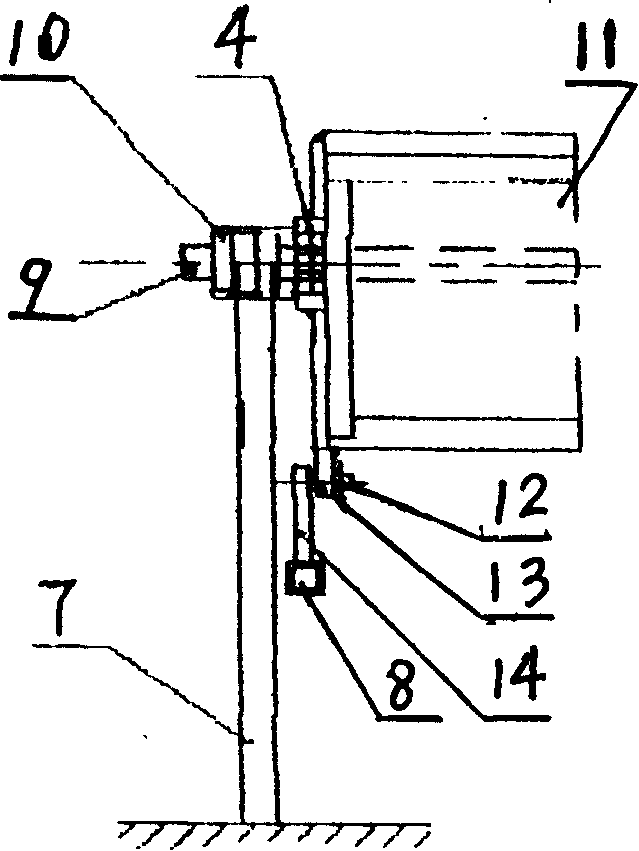
[0027] The first embodiment is the embodiment of solar boiler parabolic reflector tracking the sun. figure 1 It is a mirror support front view. figure 2 It is a mirror support side view. A heat-absorbing pipe 9 is installed at the focal line of the parabolic reflector 1 (hereinafter referred to as the reflector), and the heat-absorbing pipe 9 is connected in series and parallel to the heat exchange place; , a bearing seat 4, a flange 5, and a longitudinal rod 6. The panel 11 is fixed by the picture frame 2, and the longitudinal bar 6 is welded together with the picture frame 2. The picture frame 2 is connected to the bearing seat 4 by a tension rod 3. There is a bearing bush in the bearing seat 4. Installed on the sleeve shaft 10, the bearing pad seat 4 and the bearing pad are all up and down structures. There is a pair of flanges 5 on the bearing pad seat 4, and there are scr...


PUM


Abstract

The invention provides an automatic follow sun device and a connecting drive mechanism and relates to the solar energy utilization technical field; the automatic follow sun device is formed by that: a push-pull device of a bracket is accurately controlled by a controller to drive a ratchet wheel device intermittently; the ratchet wheel device is connected with and drives a light absorbing body to rotate and follow the sun, or an electromotor of the bracket and a clutch of a ratchet wheel row are accurately controlled by the controller; the electromotor drives the ratchet wheel row; the ratchet wheel row is connected with and intermittently drives the light absorbing body to rotate and follow the sun; a connecting drive mechanism is a mechanism which uses parallel connecting rods to hinge a plurality of parallel light absorbing bodies in parallel. The invention provides a follow device with short gearing chain, simple and reliable structure and accurate follow angle: each drive only feeds the light absorbing body to rotate several percent degrees or even a smaller angle uniformly. The invention has millions of evolvement proposals and wide application scope and can be widely used in a photovoltaic battery plate, a solar cooker, a flat plate heat collector, a solar furnace, a solar energy boiler and a solar energy utilization device to follow the sun.

Description

technical field [0001] The present application relates to the technical field of solar energy utilization, in particular to an automatic sun tracking device. Background technique [0002] In order to utilize solar energy efficiently, the normal line of the light-absorbing body must be aligned with the sun, that is, the normal line of the light-absorbing body is parallel to the direct rays of the sun; since the earth revolves around the sun on the ecliptic plane, the declination angle is formed at ±23°27′; and the earth rotates around the earth's axis, forming a solar hour angle that varies between ±180° every day, which is equivalent to a rotation of 15° per hour, so the light-absorbing body should be rotated slowly so that the normal line is always aligned with the Only the quasi-sun can efficiently utilize solar energy. The Chinese patent with the application number 03113205.7 discloses a large-scale windproof automatic tracking solar daylighting device. The main points o...

Claims


Application Information

Patent Timeline
IPC IPC(8): F24J2/38F24S50/20
CPCF24J2/38Y02E10/47F24S50/20
Inventor 陈红专
Owner 陈红专
Learn More