Executing element, valve device and air door device

A technology for actuators and retaining components, applied to valve devices, valve operating/release devices, transmission devices, etc., can solve problems such as unfavorable cost control, increased quantity, and increased complexity

Inactive Publication Date: 2008-06-25
YAMATAKE HONEYWELL CO LTD
View PDF2 Cites 2 Cited by
  • Summary
  • Abstract
  • Description
  • Claims
  • Application Information

AI Technical Summary

Problems solved by technology

[0015] However, for example, if a transmission clutch mechanism is provided on an actuator having a clutch mechanism for manual operation, the number of parts will increase as shown in FIG. large, complex, etc.
In addition, in order to adjust the speed of the driving source, it is necessary to use an expensive speed control circuit or a corresponding driving source, which is not conducive to cost control

Method used


Image

  • Executing element, valve device and air door device
  • Executing element, valve device and air door device
  • Executing element, valve device and air door device

Examples


Embodiment approach 1

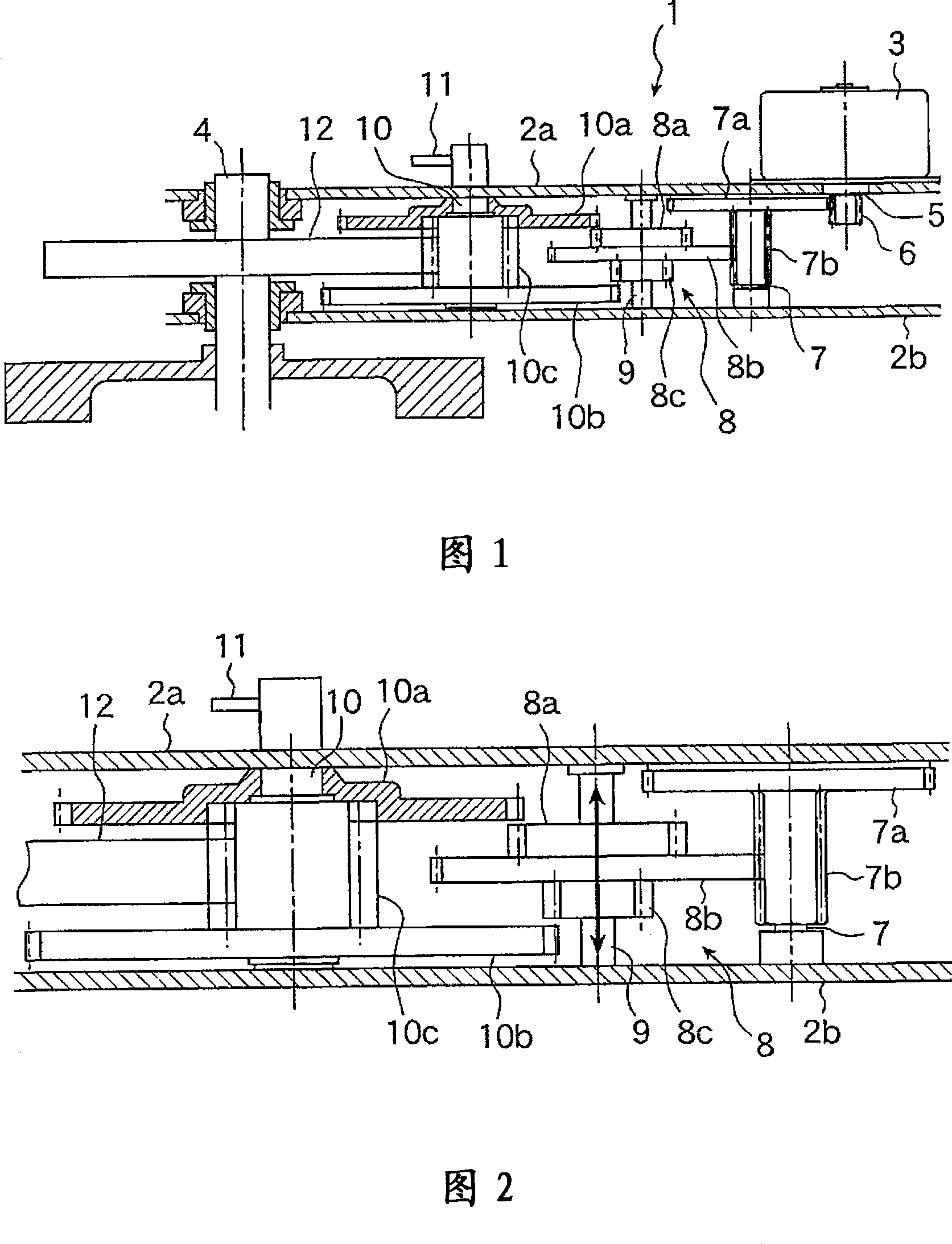
[0031] FIG. 1 is a schematic diagram showing an internal mechanism of an actuator according to Embodiment 1 of the present invention. FIG. 2 is a diagram showing a gear unit in FIG. 1 . The actuator 1 according to Embodiment 1 has: support plates 2a, 2b housed in a housing; a motor 3 disposed on the support plate 2a; and an output shaft provided on the support plates 2a, 2b so as to penetrate the support plates 2a, 2b. 4. The output shaft can rotate freely; and the gear unit that transmits the torque of the motor 3 to the output shaft 4 .

[0032] The support plate 2a and the support plate 2b are arranged in parallel and spaced apart in the casing. The electric motor 3 is arranged such that its rotary shaft 5 penetrates the support plate 2 a , and a transmission gear 6 is attached to the rotary shaft 5 . The output shaft 4 of the actuator 1 is connected to a valve stem (not shown) installed at the bottom of FIG. 1 , and the valve opens and closes in accordance with the rotat...

Embodiment approach 2

[0073] In the example shown in Embodiment 1 above, during manual operation, the connection between the manual / transmission clutch gear and the rear-stage transmission gear is cut off. The connection between the transmission gears on the front stage side.

[0074] Fig. 7 is a diagram showing a gear unit of an actuator according to Embodiment 2 of the present invention. The gear unit shown in Fig. 7 has: the transmission gear 6 fixed on the rotary shaft 5 of the motor 3, the manual / transmission clutch gear 22 with gear parts 22a, 22b, 22c, 22d, and a coaxial manner formed and can be integrated Rotating drive gears 24a, 24b, 24c.

[0075] The manual / transmission clutch gear 22 is composed of coaxially integrally formed gear portions 22a, 22b, 22c, and 22d, and is provided on the fixed shaft 23 so as to rotate around the fixed shaft 23 fixed to the support plates 2a, 2b. , and can slide along the axial direction of the fixed shaft 23. In addition, in each gear portion of the ma...


PUM


Abstract

The invention provides an executing element which achieves the manual / electric operation switching and changes the speed of an output shaft with a simple structure, as well as a valve device and a throttle device using the executing element. The executing element achieves movable operations to a manual / electric clutch gear (8) which consists of a plurality of gears which are coaxial and rotate integrally along a fixing shaft (9), thereby canceling the joggling between a front-stage side transmission gear or a rear-stage side transmission gear and the manual / electric clutch gear (8) and joggling the manual / electric clutch gear (8) and the rear-stage side transmission gear which produces a desired deceleration ratio.

Description

technical field [0001] The present invention relates to an actuator for driving and controlling a driven object by a motor, a valve device for opening and closing a valve using the actuator, and a damper device for controlling the opening and closing of a damper. Background technique [0002] In the valve operation performed by the actuator, it is necessary to adjust the valve opening by manual operation during the installation, maintenance and emergency of the valve. Therefore, the electric actuator that controls the opening or closing of the valve is often provided with a clutch mechanism for switching between electric operation and manual operation in the gear unit between the drive source such as a motor and the output shaft of the actuator. [0003] Figure 8 shows a perspective view of a valve device with an actuator, wherein the actuator has a clutch mechanism for switching between manual and electric operation modes, and (a) in Figure 8 shows that the valve 101 is equ...

Claims


Application Information

Patent Timeline
Patent Type & Authority Applications(China)
IPC IPC(8): F16K31/05F16H3/02
CPCF16K31/043
Inventor 关根浩一大桥智文
Owner YAMATAKE HONEYWELL CO LTD
Why Eureka
Try Eureka