Fixture and clamp applying same

A fixture and clamp arm technology, applied in the field of hanger structure, can solve the problems of affecting the surface quality of workpieces, reducing production efficiency, increasing costs, etc., and achieve the effect of improving surface quality, increasing productivity, and reducing surface area

Inactive Publication Date: 2008-06-25
SHENZHEN FUTAIHONG PRECISION IND CO LTD
View PDF0 Cites 5 Cited by
  • Summary
  • Abstract
  • Description
  • Claims
  • Application Information

AI Technical Summary

Problems solved by technology

When the hanger is taken out after dipping, some dyes are often accumulated on the tab 14 of the clamp 10 of the hanger, and these dyes remaining on the tab 14 will flow to the surface of the workpiece 20, leaving some extreme stains on the workpiece surface. Unsightly flow marks will affect the surface quality of the workpiece. In severe cases, the workpiece needs to be re-dipped, thereby reducing production efficiency and increasing costs

Method used


Image

  • Fixture and clamp applying same
  • Fixture and clamp applying same
  • Fixture and clamp applying same

Examples


Embodiment Construction

[0013] The fixture and hanger structure of the present invention are applied in the process of performing dip-dyeing treatment on workpieces.

[0014] The preferred embodiment of the clamp of the present invention is described by taking the structure of the hanger using the clamp as an example.

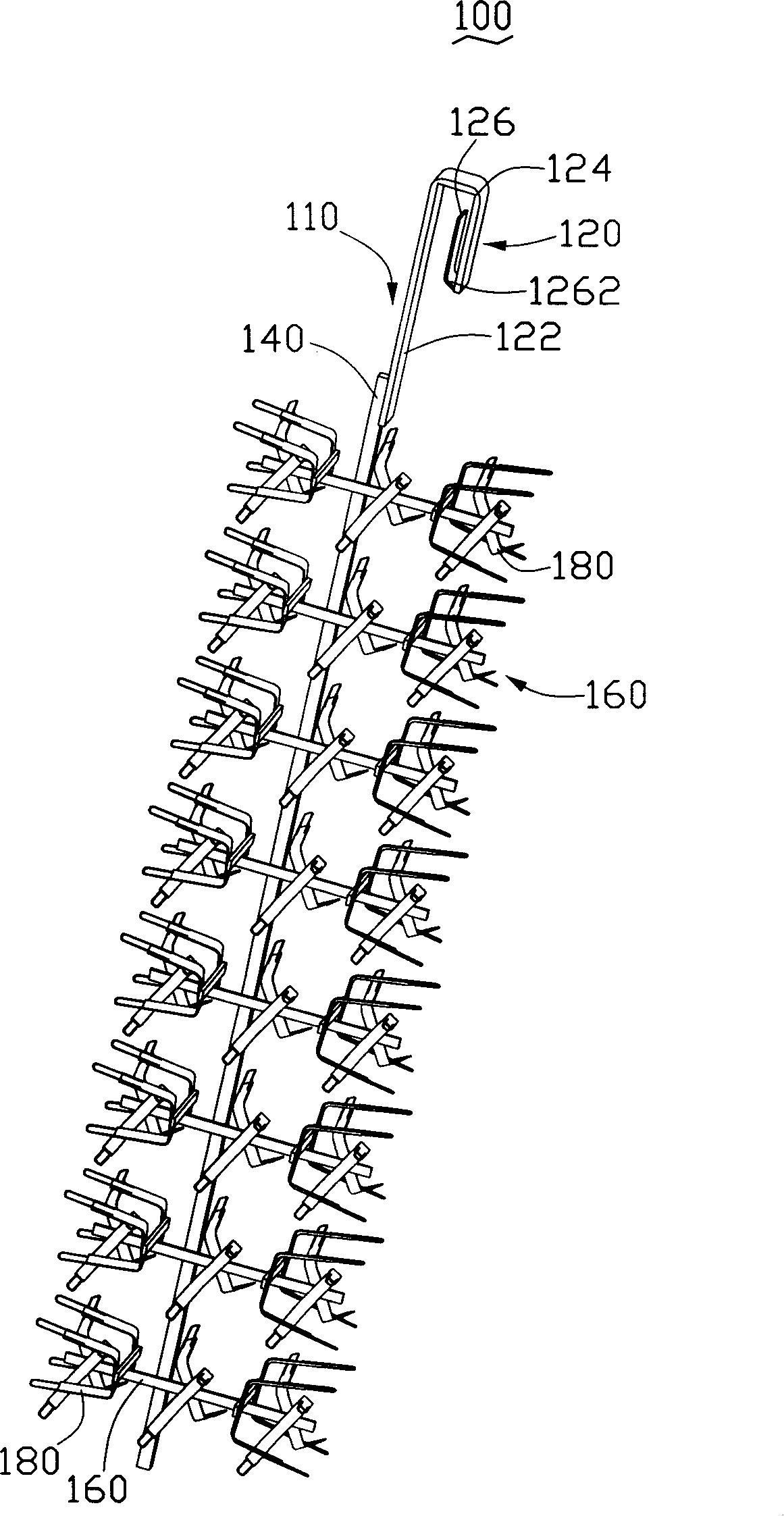
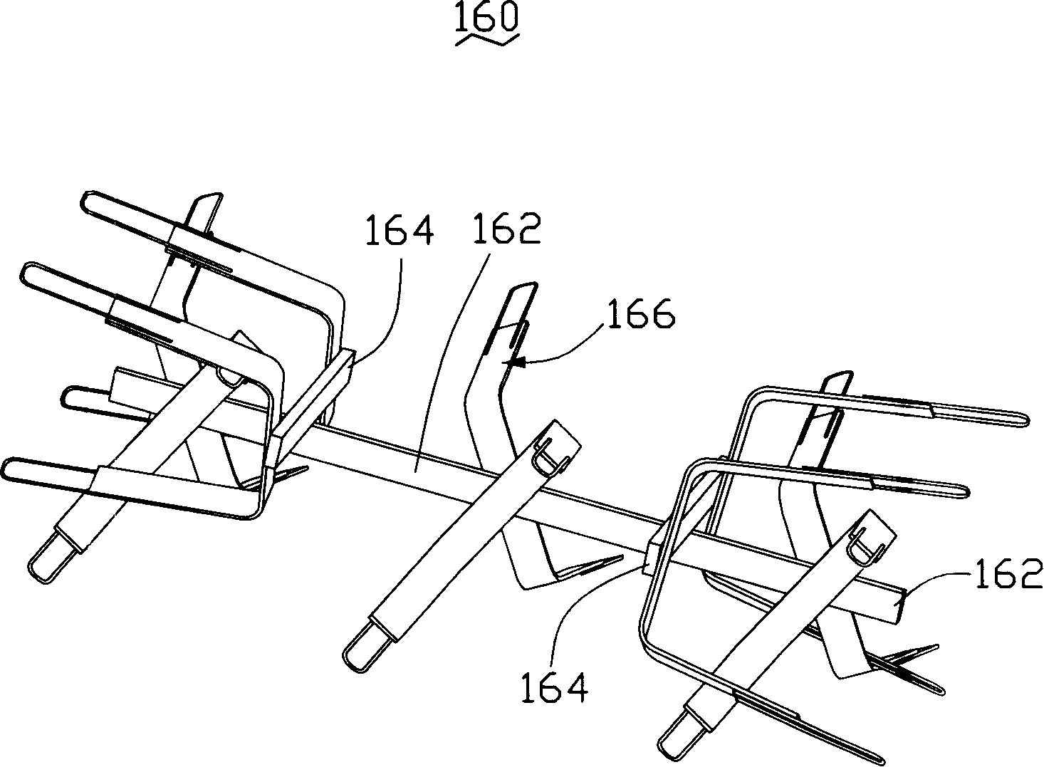
[0015] see figure 2 , the hanger structure 100 is used in anodizing and dip-dyeing processes for workpieces. The hanger structure 100 includes a hanger 110 and a plurality of sets of supports 160 , and the sets of supports 160 are equidistantly arranged on the hanger 110 .

[0016] The hanging frame 110 includes a hanging rod 120 and an extending rod 140 , one end of the hanging rod 120 is fixedly connected with one end of the extending rod 140 .

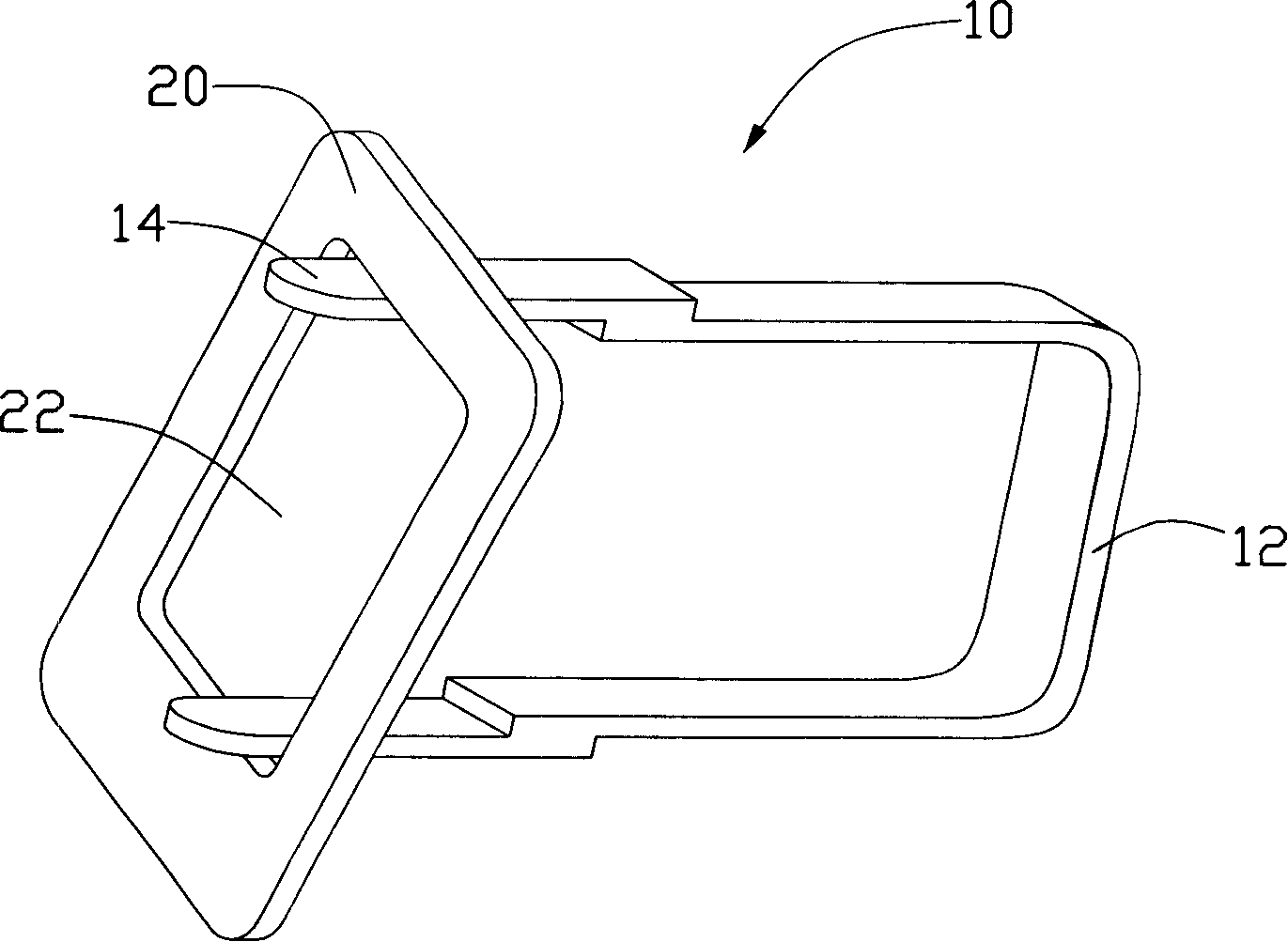
[0017] The hanging rod 120 is made of conductive material, and includes a connecting portion 122 , a hook 124 and a conductive sheet 126 . The hook 124 is disposed at one end of the connecting portion 122 . A bent portion 1262 is forme...


PUM


Abstract

The invention relates to a clamping device and a hanging tool structure applying the clamping device; wherein, the clamping device includes a clamping arm and at least two blocking clappers which are respectively arranged at the two ends of the clamping arm. The blocking clapper is provided with a fixedly connecting part arranged at the end part of the clamping arm and a clamping part extending out of the clamping arm. The clamping part is provided with at least one through hole. The claming device has the advantages of reducing the flow marks on the surface of a work-piece and improving the quality of the work-piece thereby.

Description

technical field [0001] The invention relates to a jig and a hanger structure using the jig, in particular to a jig and a hanger structure for workpiece dipping. Background technique [0002] The dip-dyeing process is widely used in the process of coloring workpieces. When dip-dyeing some workpieces, the workpieces need to be hung on the fixture of the hanger. Please refer to figure 1 , an existing hanger structure, which includes a plurality of clamps 10 supporting workpieces, each clamp 10 is made of elastic metal, it includes a clamp arm 12 and two tabs 14, and the tabs 14 are strip-shaped The metal sheet is fixed on the clamp arm 12 . When in use, the tabs 14 of the fixture 10 are relatively close together and then protrude into the opening 22 of the workpiece 20, and are stuck on the opposite corners of the square opening 22, thereby clamping the workpiece 20. After the workpiece is clamped, the fixture 10 and the workpiece 20 are put into the dipping tank together wit...

Claims


Application Information

Patent Timeline
IPC IPC(8): B05C3/02B05C13/02
CPCB05C13/00B05C3/09
Inventor 林知本张勇洪云朱展刚胡群高
Owner SHENZHEN FUTAIHONG PRECISION IND CO LTD
Why Eureka
Try Eureka