Steering adjustment screw retainer

A technology of bolts and retaining pieces, applied in the field of adjustment structures, which can solve problems such as not allowing rapid adjustment

Inactive Publication Date: 2008-06-11
CLARK EQUIP CO INC
View PDF1 Cites 2 Cited by
  • Summary
  • Abstract
  • Description
  • Claims
  • Application Information

AI Technical Summary

Problems solved by technology

Currently, existing skid steer arrangements do not allow for quick adjustments in the full forward speed position of both steering rods to set and match the speed of the two opposite side motors of the loader

Method used


Image

  • Steering adjustment screw retainer
  • Steering adjustment screw retainer
  • Steering adjustment screw retainer

Examples


Embodiment Construction

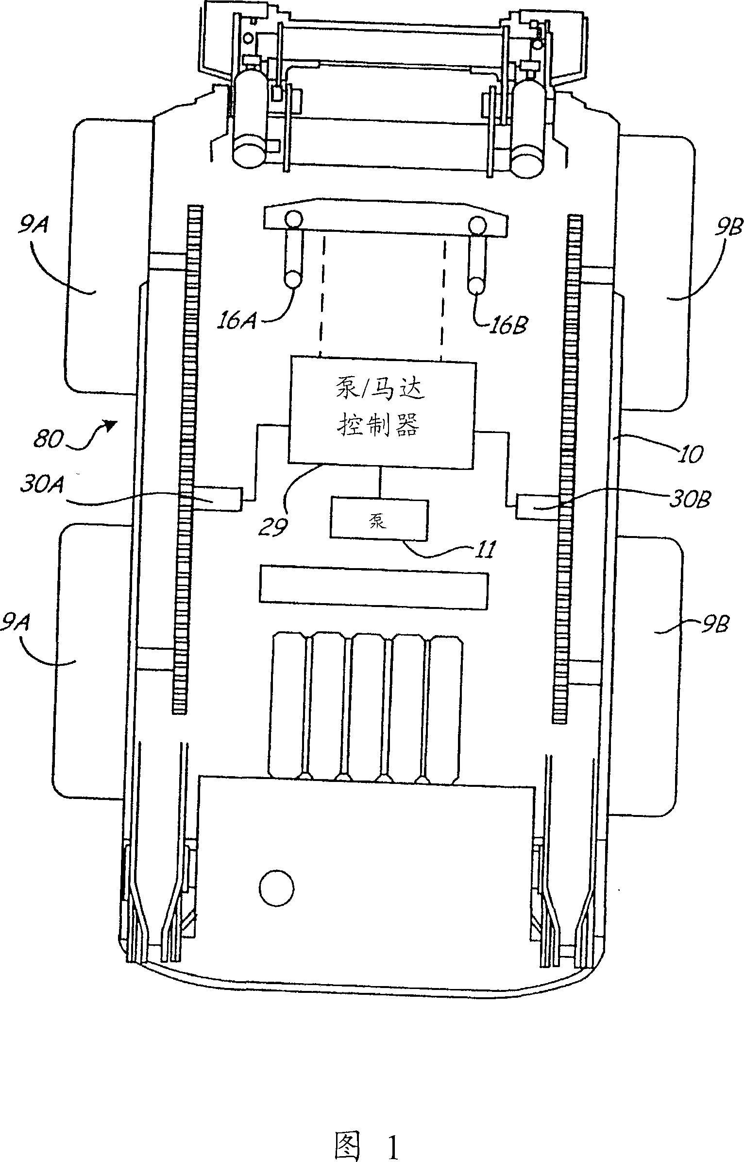
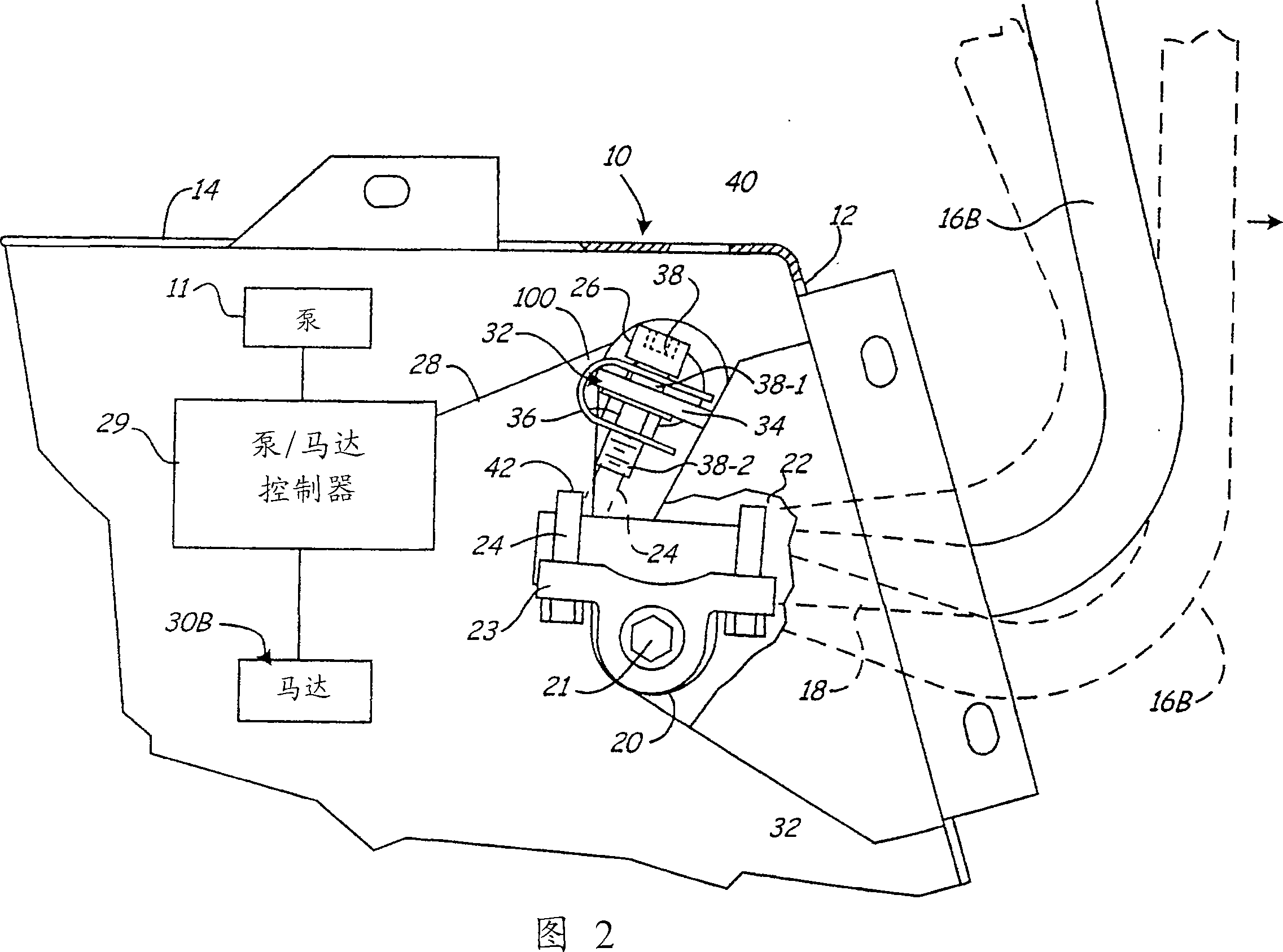
[0014] The use of a pair of control levers to control the movement of skid and turn loaders is known. Figures 1 and 2 respectively depict a skid steer vehicle including a loader 80 as shown and described, having wheels driven in pairs and comprising a pair of left wheels 9A and a pair of right wheels 9B. The loader 80 has a frame 10 supporting an engine that powers a pump 11 to provide pressurized fluid to a controllable drive motor and other components.

[0015] Drive control levers or rods 16A, 16B are rotatably mounted on shafts under the operator or cab platform 12 and extend into the cab. Each side of the loader is driven by separate controlled flow and variable speed (swash plate) motors 30A, 30B. The speed of the motors 30A, 30B depends on the position of the respective steering rod. As can be seen in the figure, the motor 30A simultaneously drives the two wheels 9A, and the motor 30B simultaneously drives the two wheels 9B.

[0016] In the intermediate position of t...


PUM


Abstract

A retaining strip arranged to impede the rotation of a stop screw is disclosed. The retaining strip connects with the stop screw on both sides of an attachment bracket. The retaining strip is stretched over the bracket and applies a pressure to the screw that serves to maintain screw rotational position during vehicle operation. The retaining strip does not hamper the adjustment of the screw during adjustment.

Description

technical field [0001] The present invention relates to an adjustment mechanism that adjusts the rotational speeds of drive wheels on opposite sides of a skid steer vehicle or loader to match when the existing steering lever is in the full forward position. An adjustable travel limiter that adjusts the maximum speed position of the drive controller for the drive motor on one side of the vehicle is accessible from inside the loader cab to allow easy manual adjustment. When both drive controls are in the maximum speed position, the drive speeds on both sides of the skid steer match and the loader will drive straight ahead. Background technique [0002] Historically, the hydrostatic drive system of existing skid steers has been operated by a pair of levers in the cab that move forward or rearward from a neutral position. This lever turns a bell crank on an axle mounted on the loader. These bell cranks are connected to linkages leading to respective pump / motor controllers on o...

Claims


Application Information

Patent Timeline
Patent Type & Authority Applications(China)
IPC IPC(8): B62D11/18
CPCE02F9/2004B62D11/006B62D11/04F16B39/10Y10T74/2063Y10T74/20636
Inventor 科里·L·福恩斯迈克尔·保罗·兰塞思
Owner CLARK EQUIP CO INC
Why Eureka
Try Eureka