Electric leakage current breaker

A leakage circuit breaker and electric technology, applied in the field of leakage protectors, can solve the problems of high cost and cost, damage to the operating handle, etc., and achieve the effects of low cost, good buffering effect and simple structure

Inactive Publication Date: 2011-01-19
赵建清
View PDF3 Cites 0 Cited by
  • Summary
  • Abstract
  • Description
  • Claims
  • Application Information

AI Technical Summary

Problems solved by technology

[0007] The above three types of earth leakage circuit breakers that can realize electric closing and opening require fine processing of the electric transmission mechanism, and the cost and cost are relatively high; in addition, the electric transmission needs to control the transmission distance, because if the transmission rod transmission distance If the transmission distance is small, the operating handle cannot be changed from one working state to another; and when the transmission distance is large, the operating handle will be damaged due to excessive force.

Method used


Image

  • Electric leakage current breaker
  • Electric leakage current breaker
  • Electric leakage current breaker

Examples


Embodiment 1

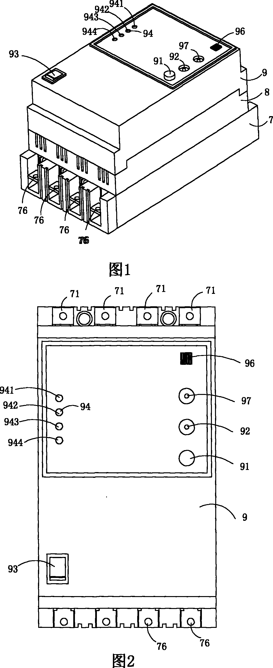
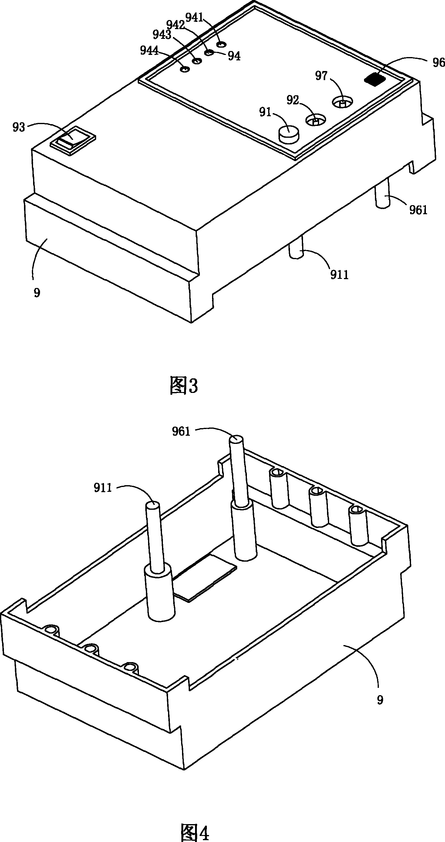
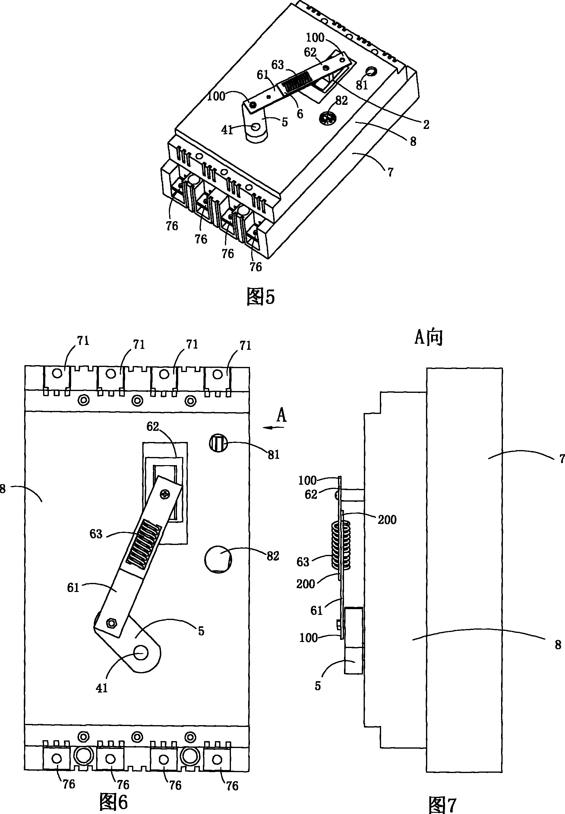
[0042] Figure 1 to Figure 15 A first embodiment of the invention is shown, in which figure 1 It is a schematic diagram of a three-dimensional structure of the present invention; figure 2 yes figure 1 The structural diagram of the electric leakage circuit breaker shown when viewed from the front; image 3 yes figure 1 A schematic diagram of a three-dimensional structure of the upper cover in the electric leakage circuit breaker shown; Figure 4 yes image 3 The schematic diagram of the three-dimensional structure of the upper cover when viewed from another angle; Figure 5 yes figure 1 A schematic diagram of the three-dimensional structure of the electric leakage circuit breaker after the upper cover is removed; Image 6 yes Figure 5 The structural diagram of the earth leakage circuit breaker shown when viewed from the front; Figure 7 yes Image 6 A-direction view; Figure 8 yes figure 1 A schematic diagram of a three-dimensional structure of the middle cover in...

Embodiment 2

[0049] Figure 16 to Figure 17 A second embodiment of the invention is shown, in which Figure 16 It is a schematic diagram of a three-dimensional structure of the arc chute in the second structure of the present invention; Figure 17 yes Figure 16 The three-dimensional structural schematic diagram of the arc extinguisher shown when viewed from another angle.

[0050] This embodiment is basically the same as Embodiment 1, the difference is: see Figure 16 with 17 , the base 7 is also provided with current transformers (not shown in the figure) with the same number of soft connection copper wires of each phase line, and the soft connection copper wires of each phase line pass through the corresponding current transformers. Arc extinguishing covers 78 are also provided at the fixed contacts 72 . The control circuit board of the earth leakage circuit breaker body 1 is at least two separate circuit boards, and is arranged on the upper cover 8 or the middle cover 9 .

[0051...


PUM


Abstract

The invention discloses a dynamic type leakage circuit breaker, which comprises a leakage circuit breaker main body which is provided with an operation handle and a dynamic type drive mechanism which is used for driving the operation handle. The dynamic type drive mechanism comprises a motor, an eccentric wheel and a buffer type drive rod component, and the eccentric wheel is arranged on an output shaft of the motor; one end of the buffer type drive rod component is connected with the eccentric wheel, and the other end is connected with the operation handle. The invention has the advantages of simple structure and lower cost, and overcomes the defect that the operation handle of a traditional dynamic type leakage circuit breaker is damaged because of excessive force.

Description

technical field [0001] The invention belongs to the technical field of leakage protectors, and in particular relates to a leakage circuit breaker. Background technique [0002] Leakage circuit breaker is a circuit breaker that can automatically disconnect the circuit when the residual current reaches or exceeds the specified value under specified conditions, and is used to prevent personal injury, equipment damage, fire and other accidents caused by electric shock and leakage. [0003] In addition to the traditional leakage circuit breaker can complete the function of automatic opening when the leakage or overload exceeds the preset value, manual operation is required to achieve opening or closing at other times. For example, a leakage circuit breaker disclosed in Chinese patent 200620105204.2 is equipped with an arc extinguisher, contacts, leakage release, overcurrent release, soft connection copper wire, current transformer, and zero-sequence current transformer in its bas...

Claims


Application Information

Patent Timeline
Patent Type & Authority Patents(China)
IPC IPC(8): H01H83/14H01H71/04H01H71/02H01H71/08H01H71/50H01H71/70
Inventor 赵建清
Owner 赵建清
Why Eureka
Try Eureka