
ARM-based flat wheel detection and control system

A technology of detection and control system and flat wheel, applied in signal transmission system, electrical signal transmission system, instrument, etc., can solve the problems of reduced efficiency and real-time performance, construction cost, maintenance cost, high expansion cost, and increased design difficulty. Achieve the effects of improving system stability and reliability, tailorable real-time performance and reliability, excellent real-time performance and reliability

Inactive Publication Date: 2008-05-28
HARBIN ENG UNIV
View PDF0 Cites 5 Cited by
  • Summary
  • Abstract
  • Description
  • Claims
  • Application Information

AI Technical Summary

Problems solved by technology

[0003] Over the years, many countries have made unremitting efforts to realize the dynamic detection of wheel flat scars, and put forward various schemes, but the methods commonly used by the monitoring platform are mainly completed by industrial computers or PCs, and the front end mainly uses The A / D conversion circuit collects data, and then the main algorithm and judgment work are left to the industrial computer to complete. In a sense, this approach does not have a separate overall system control process, and the collected data is completely handed over to the industrial computer. Although it has comprehensive functions, it has many unfavorable factors, such as large size, difficult expansion, high construction cost, maintenance cost and expansion cost, and it is not conducive to on-site observation
[0004] At present, some foreign technical methods have begun to move part of the work of the industrial computer to the front-end DSP data acquisition board to perform most of the algorithm processing. However, due to the complexity of the algorithm and a large number of controls, the efficiency and real-time performance are limited. It is reduced, and this requires the use of high-performance DSP chips, which require high configuration conditions, which increases the cost and makes the design more difficult. Therefore, a reasonable configuration structure and some new design methods are adopted. For the flat wheel The design and application of the detection platform is of great significance

Method used


Image

  • ARM-based flat wheel detection and control system
  • ARM-based flat wheel detection and control system
  • ARM-based flat wheel detection and control system

Examples


Embodiment Construction

[0024] The present invention is described in more detail below in conjunction with accompanying drawing example:

[0025] 1. Hardware part:

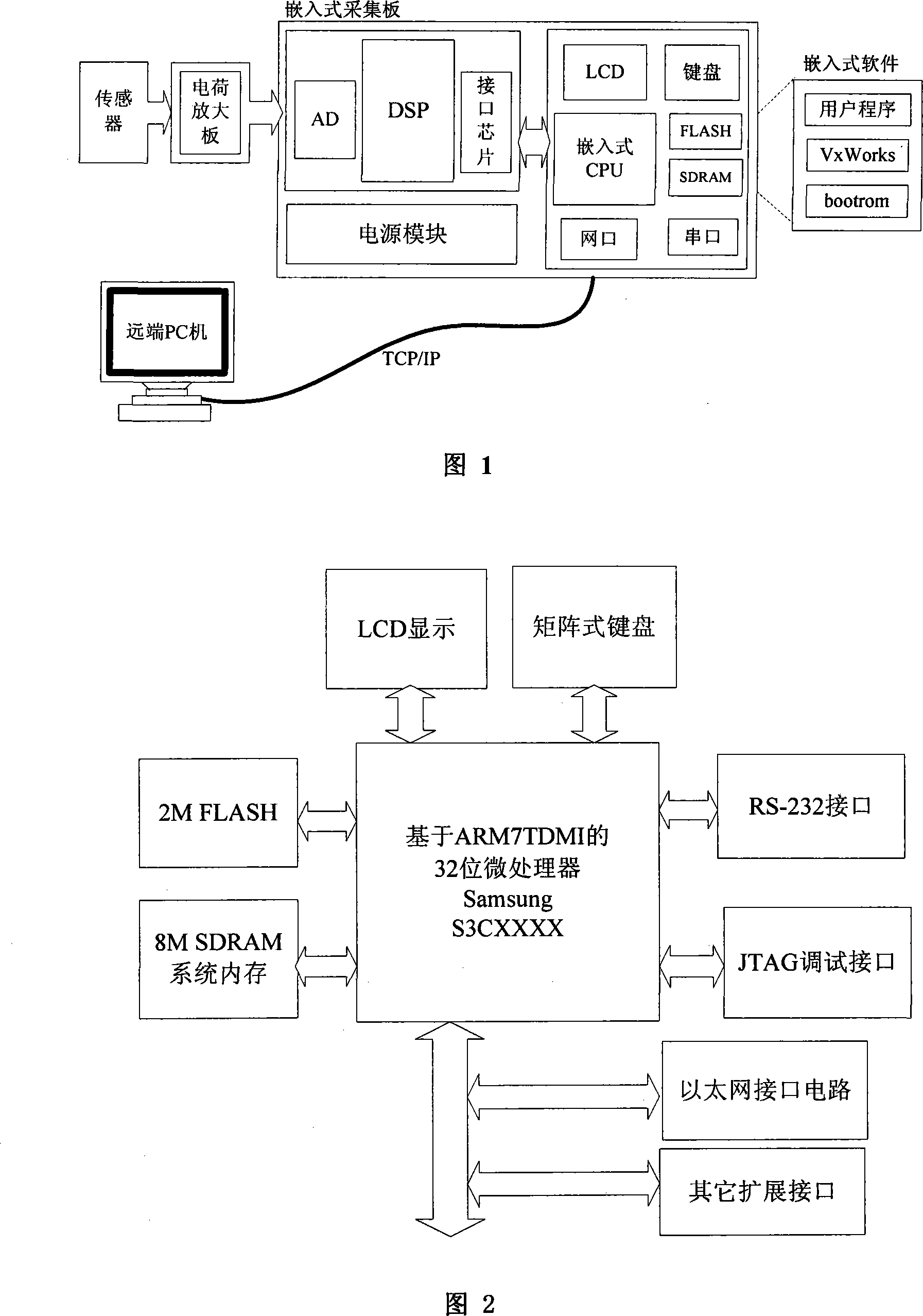
[0026] Combined with Figure 2, the specific details are as follows:

[0027] 1) The embedded main CPU adopts the representative microcontroller S3CxxB0 with ARM7TDMI core of Samsung Company, and the maximum main frequency can reach 66MHz.

[0028] 2) The 8M memory SDRAM adopts HY57V64xxxx, which is used as the space for the system code to run, namely: [0x0C000000~0X0C800000]. The data lines D15~D0 are connected to the main chip data lines DATA15~DATA0, the address lines A11~A0 are connected to the main chip address lines ADDR12~ADDR1, and the control lines are respectively connected to the main chip nWBE0, nWBE1, nSCKE, nSCLK, nSCS0, nSRAS, nSCAS connected.

[0029] 3) 2M FLASH[0x00000000~0X00200000] is used for curing program, using AM29LVxxxDB, its data lines D15~D0 are connected with main chip data lines DATA15~DATA0, address lines...


PUM


Abstract

The invention relates to a face cam test and control system, which is based on the ARM. The system mainly comprises a power supply, a crystal, a reset circuit, an ARM, consisting of JTAG ports and working as an embedded CPU which is connected with FLASH and SDRAM; the invention also comprises a power-supply module, a buzzer, indicators, an eight-section nixietube and a system expansion bus, which are all connected with the embedded CPU. By using the distinctive features of the technology used in embedded products, the invention has self advantages of in size and power consumption. The invention does not have the problems such as crashes and upgrades, but has simpler and more convenient operation interfaces and operation manners, and relatively long lifecycle.

Description

(1) Technical field [0001] The invention relates to a railway detection device, in particular to a flat wheel detection system. (2) Background technology [0002] With the continuous improvement of railway transportation capacity, the railway department urgently needs real-time monitoring of transportation vehicles, and puts forward higher requirements for the safety, efficiency and intelligence of railway inspection equipment. Wheel flat scars are one of the hidden dangers of major train accidents. Therefore, it is of great significance to the development and research of flat wheel detection platforms [0003] Over the years, many countries have made unremitting efforts to realize the dynamic detection of wheel flat scars, and put forward various schemes, but the methods commonly used by the monitoring platform are mainly completed by industrial computers or PCs, and the front end mainly uses The A / D conversion circuit collects data, and then the main algorithm and judgmen...

Claims


Application Information

Patent Timeline
Patent Type & Authority Applications(China)
IPC IPC(8): G08C19/00
Inventor 张兴周韩亮张博为靳庆贵战永兴杨志刚田金超王鹏飞胡文飞
Owner HARBIN ENG UNIV
Learn More