Combination type drawer affair cabinet
A combined, drawer technology, applied in drawers, cabinets, chests of drawers, etc., can solve problems such as uneconomical benefits, unfavorable storage space and transportation, and increased production costs, and achieve the effect of reducing manufacturing costs.
Inactive Publication Date: 2010-11-10
HAW JOU ENTERPRISE
View PDF0 Cites 0 Cited by
- Summary
- Abstract
- Description
- Claims
- Application Information
AI Technical Summary
Problems solved by technology
However, for the mechanism of the above-mentioned known fixed cabinet drawers, in the manufacturing process, it is necessary to perform appropriate concave folding on the end edges of each board to form a board edge that provides a connection position, and the corresponding joint board The edge is welded and fixed, which will easily increase the production cost, and the overall volume of the finished cabinet and drawer has been limited and cannot be changed, so it is not conducive to storage space and transportation, and is not economical.
Method used
View moreImage
Smart ImageViewing Examples
Examples
Embodiment Construction
Login to View More PUM
 Abstract
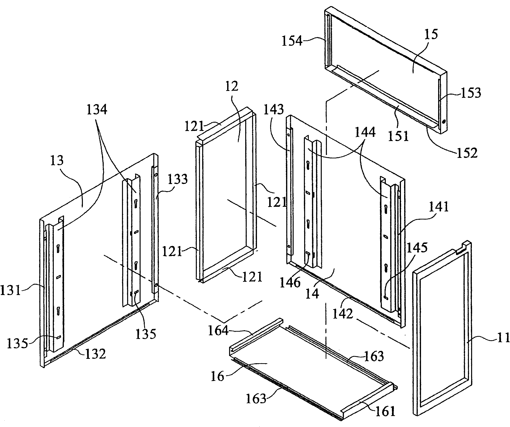
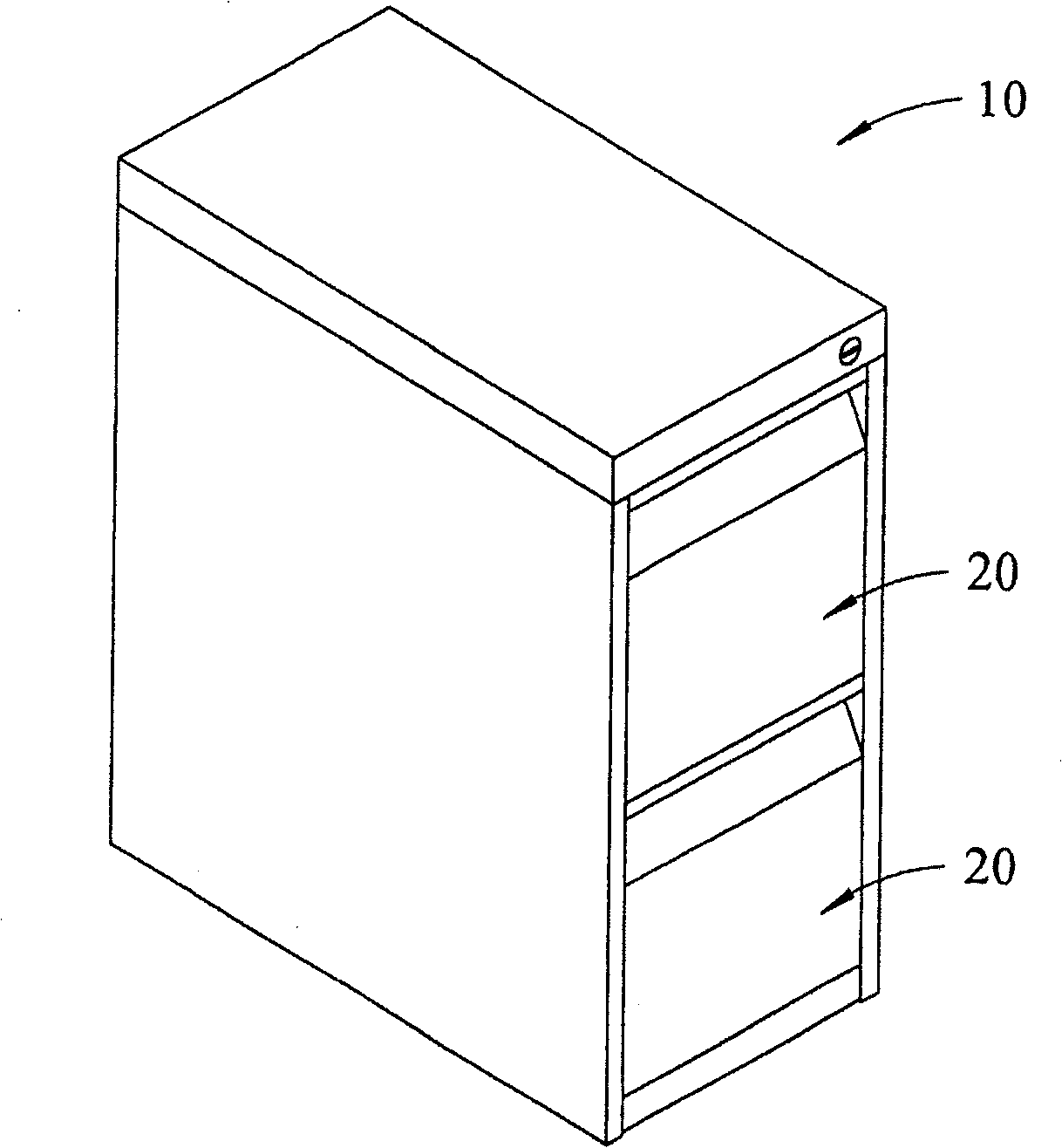
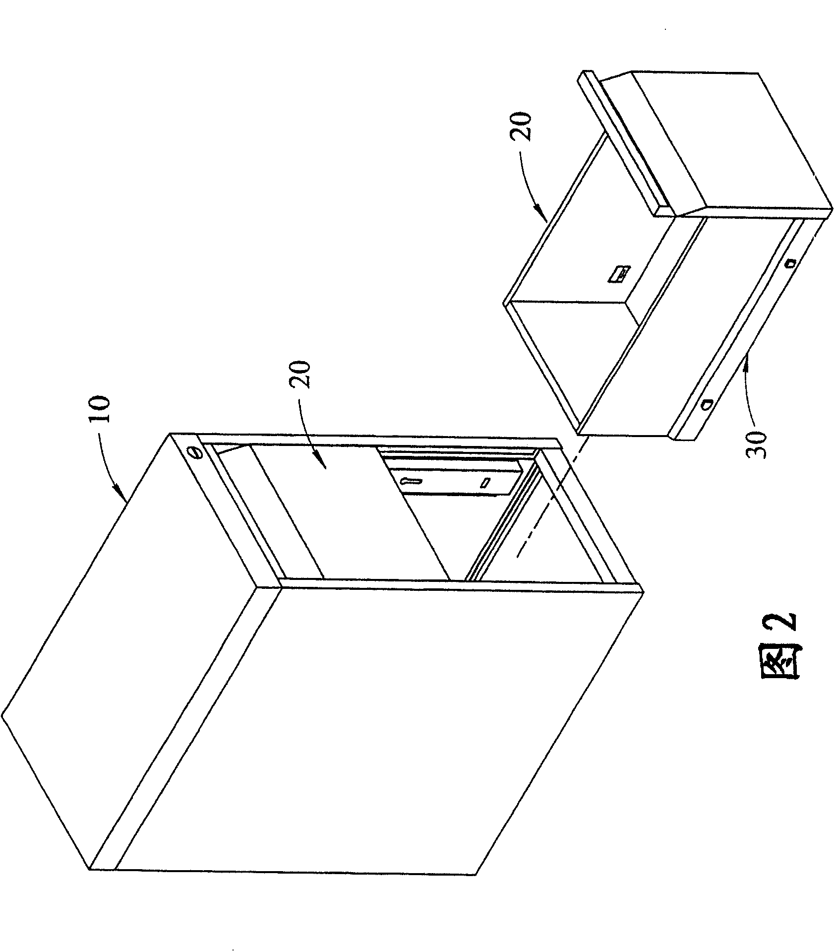
The invention discloses a cabinet with combined drawer for transaction, which consists of a cabinet body and a drawer group. The cabinet body is composed of a binding frame, a back cabinet plate, two side cabinet plates, a upper cabinet plate and a lower cabinet plate; wherein, the binding frame is enclosed by tube body, four sides of the frame are embedded into the end edge grooves connected with the anterior of the upper cabinet plate, the lower cabinet plate and the two side cabinet plates; the end edge grooves by which each cabinet plate connects with each other are respectively bended into at least a mesh edge and a binding groove. The two sides of the drawer are connected with the side plates of the cabinet body by slide rails respectively. The drawer comprises a front plate, two side plates, a bottom plate, and a back plate, wherein, drawer plates connected with each other are respectively bended into at least a mesh edge and embedded into at least a binding groove. Due to the composition, the plates of the cabinet body and the drawer can be formed independently, the connection and organization can be completed simply and quickly, which leads to the convenience of storage and transfer as a whole.
Description
Combined drawer office cabinet technical field The present invention relates to a drawer service cabinet mechanism, in particular to a snap-in engagement structure applied between a cabinet body and a drawer body, so that the cabinet body and the drawer mechanism have a simplified component manufacturing process and can be assembled quickly. At the same time, it is a combined drawer office cabinet that is beneficial to the transportation of the finished product and saves storage space. Background technique The mechanism of the drawer office cabinet is mainly composed of a cabinet body and a drawer group to provide a space for storing items, so as to achieve the effect of tidy and beautifying the indoor space; at present, the office cabinet can be roughly divided into three types in terms of its assembly technology Fixed type and combined type. The fixed type is to assemble the boards of the cabinet and drawer into a finished product in an actual use state at the same time ...
Claims
Login to View More Application Information
Patent Timeline
 Patent Type & Authority Patents(China)
IPC IPC(8): A47B67/00A47B88/00
Inventor 吴结利
Owner HAW JOU ENTERPRISE
Features
- Generate Ideas
- Intellectual Property
- Life Sciences
- Materials
- Tech Scout
- Unparalleled Data Quality
- Higher Quality Content
- 60% Fewer Hallucinations
Learn More Browse by: Latest US Patents, China's latest patents, Technical Efficacy Thesaurus, Application Domain, Technology Topic, Popular Technical Reports.
© 2025 PatSnap. All rights reserved.Legal|Privacy policy|Modern Slavery Act Transparency Statement|Sitemap|About US| Contact US: help@patsnap.com


