Axial direction free spin device

A rotating device and free technology, applied in the direction of measuring devices, instruments, surveying and navigation, etc., can solve the problems of affecting the measurement effect, suspension frame skew, bearing wear, etc., to achieve obvious functional practicability, simplified components, and structure reasonable effect

Inactive Publication Date: 2008-05-14
顺阳激光仪器(上海)有限公司
View PDF0 Cites 3 Cited by
  • Summary
  • Abstract
  • Description
  • Claims
  • Application Information

AI Technical Summary

Problems solved by technology

However, the advantage of smooth swing mentioned in this prior patent application is actually only applicable to the initial stage of use, because this structural form of the suspension frame supported by bearings will generate strong friction between the components during work, which is very easy to Wear the bearing, and the worn bearing will inevitably cause the suspension frame to skew, which will seriously affect the measurement effect
Therefore, the drawbacks in the use brought by the deficiencies of this known patent have a need to be further improved

Method used


Image

  • Axial direction free spin device
  • Axial direction free spin device
  • Axial direction free spin device

Examples


Embodiment 1

[0037] Embodiment 1 Biaxial rotation type

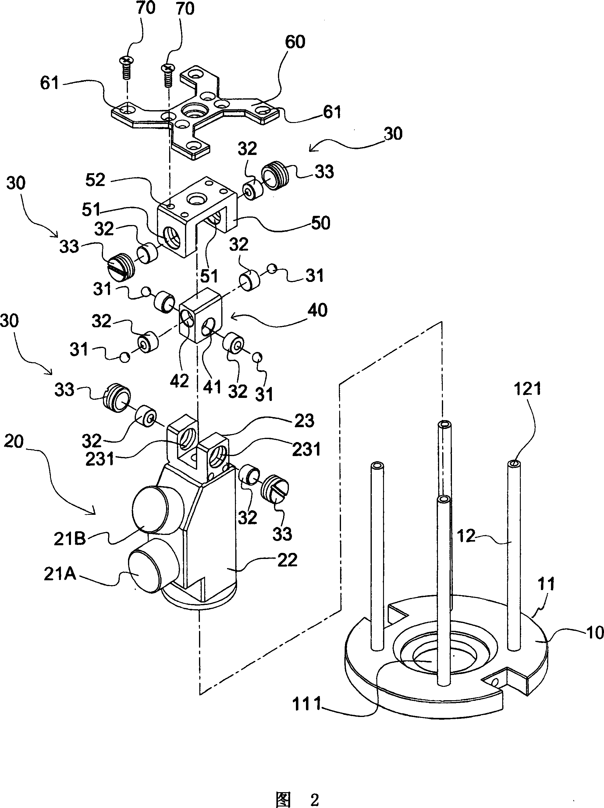
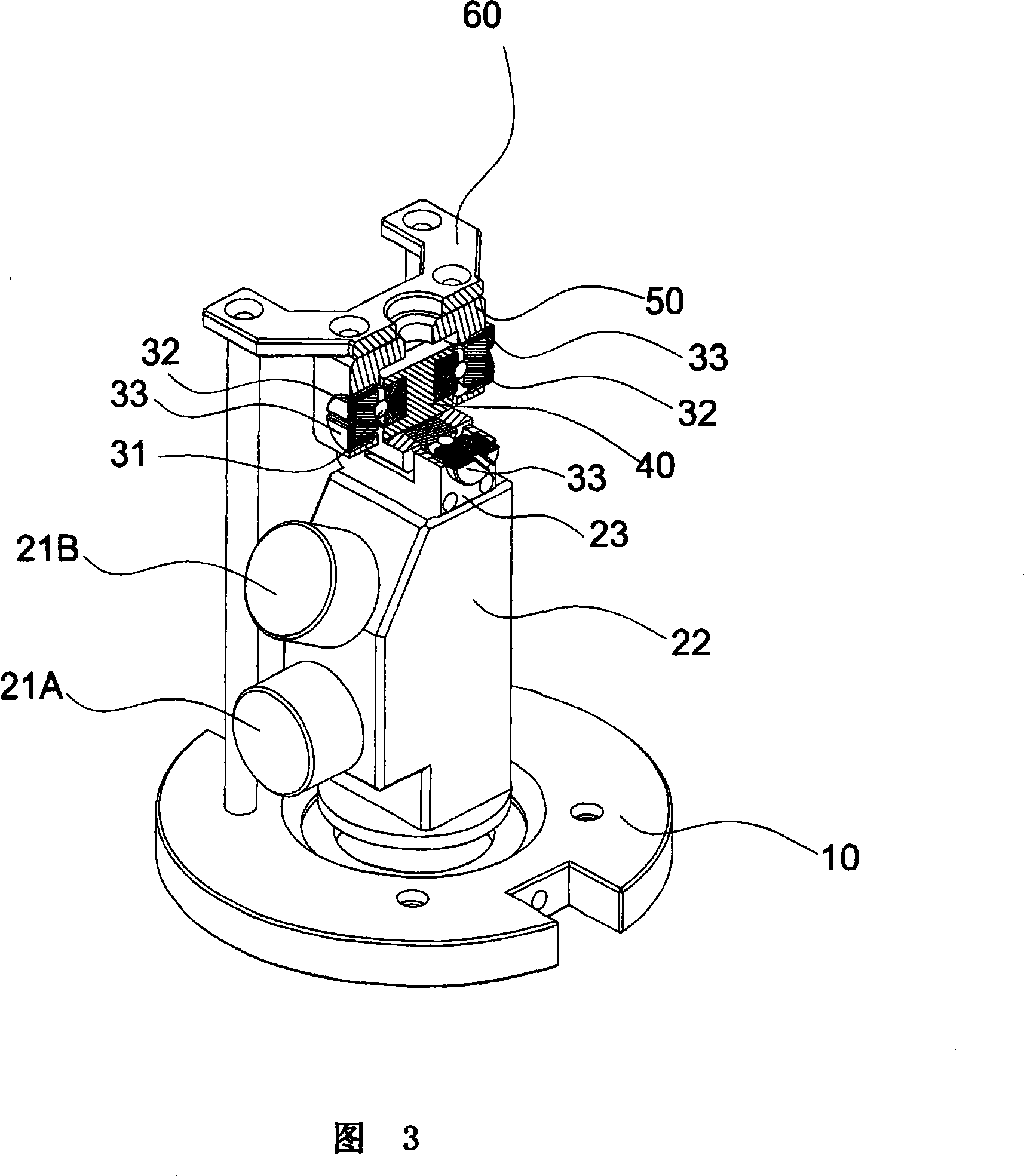
[0038] What Fig. 1-8 shows is the first embodiment of the axial free rotation device of the present invention, in Fig. 1, Fig. 2, Fig. 3 and Fig. 4, the axial free rotation device of the present invention comprises: a by above There is a circular base 11 with a step-shaped central pair of perforations 111, four uprights 12 arranged in a rectangular shape, each with a mounting screw hole 121 on the top, and a fixed member 10 composed of a fixed mounting piece 60 for assembly and connection; One includes a main body 22, two laser modules 21 located on the side of the main body 22, consisting of a horizontal laser module 21A and a vertical laser module 21B, and a horizontal through screw hole 231 coaxially arranged on the left and right sides The laser assembly 20 of the top U-shaped piece 23; one left and right sides are provided with a coaxial not penetrating transverse hole 41, and the front and rear sides are provided with a coaxial...

Embodiment 2

[0043] Embodiment 2 single-axis rotation type

[0044] 9-13 show the second embodiment of the axial free rotation device of the present invention, the single axial rotation type axial free rotation device. Its main feature is that the U-shaped part 23 in Embodiment 1 is removed, the swing member 40, the rolling member 30 are reduced from the original four groups to two groups, and the laser module 21 is reduced from the original two groups to one group (that is, only A vertical or horizontal laser module 21C) is set, and the top of the main body 22 of the laser assembly 20 is provided with a protruding shaft member 24 that is coaxially recessed on the front and rear sides and does not penetrate the longitudinal hole 241, so as to install the rolling members correspondingly The single-end concave cylinder 32 in 30 is not penetrated in the longitudinal hole 241, and the spherical ball 31 in the rolling member 30 is arranged on the outer concave surface of the single-end concave ...


PUM


Abstract

The invention relates to an actuator rotating freely along the axial direction which includes a fixed structure component, a swing component arranged in the fixed structure component, a laser component which is arranged on the lower bottom part of the swing component and can swing along the X shaft direction and Y shaft direction opposite to the swing component, and a plurality of groups of rolling components, each group of which comprises a round bead, two columns with concave and an assembling bolt. At least one laser model group is arranged in the laser component. As the actuator rotating freely along the axial direction of the invention works in the mode of universal bearing, when the invention is used in the operation of automatic laser level or engineering construction measuring, the benchmarks of a horizontal line and a vertical line can be acquired accurately under the state that the swing gets a high repetitiveness and a high sensitivity. The invention has the advantages of scientific, reasonable and simple structure, reliable work and convenient use. The invention has indeed positive technical effects of smooth swing, tidy component and precise measuring.

Description

technical field [0001] The invention relates to a measuring device, especially a measuring device used for automatic laser level or engineering construction, which can make the swing in a state of high repeatability and high sensitivity, so as to accurately obtain the axial direction of the horizontal line reference or vertical line reference. Free turning device. Background technique [0002] The laser measuring instruments in the currently known measuring devices are all supported by bearings and suspended on the body, and the movable shaft of the laser beam projector is installed on the suspension, so that the laser beam projector can swing at multiple angles, which is convenient The laser beam is projected onto the target location. [0003] The known laser measuring instrument as mentioned above has been disclosed in the utility model patent specification of Taiwan No. M304654 "Suspension Mechanism of a Laser Measuring Instrument". What this known utility model patent r...

Claims


Application Information

Patent Timeline
IPC IPC(8): G01C15/00G01C15/14
Inventor 李能焯
Owner 顺阳激光仪器(上海)有限公司
Why Eureka
Try Eureka