
Principal shaft of low-speed direct driving type aerogenerator

A wind turbine, direct-drive technology, applied to shafts, electrical components, electromechanical devices, etc., can solve the problems of high material cost, long production cycle, and high manufacturing cost, and can ensure bending and torsion resistance. The effect of reducing the material and reducing the manufacturing cost

Inactive Publication Date: 2008-05-07
刘宝生 +1
View PDF0 Cites 1 Cited by
  • Summary
  • Abstract
  • Description
  • Claims
  • Application Information

AI Technical Summary

Problems solved by technology

[0002] At present, the main shaft of wind turbines on the market is the key component of wind turbines, and the technology of solid shaft is mostly used. This kind of solid shaft is not only heavy and consumes a lot of materials, but also requires forgings due to the special manufacturing materials, and has a great impact on the performance of forgings. The requirements are extremely demanding, and a high level of processing technology is required. Therefore, not only the material cost is high and the price is expensive, but also there are difficult problems such as high manufacturing cost, large investment, and long production cycle. Therefore, the traditional design structure of the main shaft of the wind turbine has been The development of wind power generation equipment is hindered, and there is an urgent need for new breakthroughs in the structure and manufacturing process of key components of the main shaft

Method used


Image

  • Principal shaft of low-speed direct driving type aerogenerator

Examples


Embodiment Construction

[0016] The present invention will be further introduced below in conjunction with the accompanying drawings and specific embodiments, but not as a limitation of the present invention.

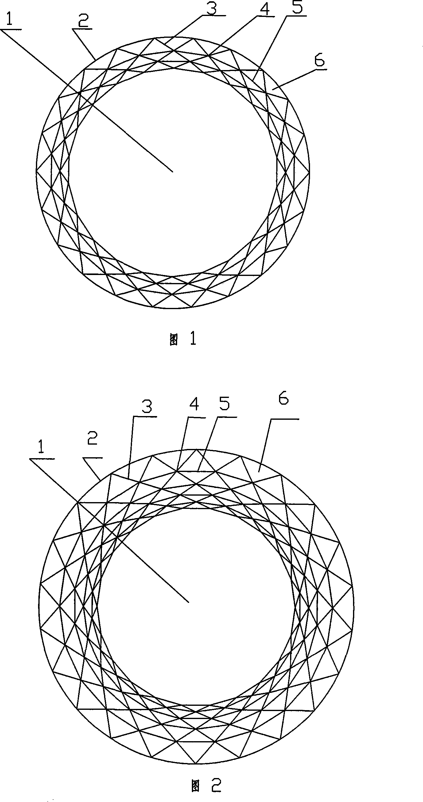
[0017] Figure 1 is a low-speed direct-drive wind turbine main shaft, in Figure 1, made of steel plate, angle steel, the main shaft 1 is a welded structure of a hollow cylinder, its cross-section is circular, the cylinder of the cylinder Part of it is composed of honeycomb grid-like cavity columns arranged regularly in the same direction. Firstly, the outer cylinder 2 made of a 20mm steel plate is rolled by a plate rolling machine, and the cylinder part of the cylinder is welded in sequence around the inner wall of the outer cylinder 2 rolled by the steel plate using 22 long angle steels 3, and welded on the outer wall of the outer cylinder 2. The minimum side width of the angle steel around the inner wall of the cylinder 2 is a right-angle steel with a side length of 120mm, equal sides and equa...


PUM


Abstract

The present invention relates to a wind-driven generator, in particular to a low-speed straight wind-driven generator principal axis, and provides a novel low-speed straight wind-driven generator principal axis with a principal-axis structure and the main body composed of a grid cylinder, including a steel plate and an angle plate. The principal axis is a hollow cylinder and the cross section is circular; the cylindrical part of the cylinder is composed of honeycomb hollow cylinders arranged equidirectionally, thus reducing the deadweight of the principal axis, shortening the production cycle, reliably ensuring the bending and twisting resistance of the axis and decreasing the bearing capacity of the tower without affecting the bearing capacity, mechanical intensity and reliability; the material for producing the principal axis is reduced and no special material is needed, thus reducing the production cost, accelerating the production and shortening the production cycle, so the materials can meet the operational requirement of the straight wind-driven generator without undergoing the forging process; in addition, the grid cylindrical hollow structure is conducive to air radiation, which is economical and reliable.

Description

technical field [0001] The invention relates to a wind power generator, in particular to a low-speed direct-drive wind power generator main shaft. Background technique [0002] At present, the main shaft of wind turbines on the market is the key component of wind turbines, and the technology of solid shaft is mostly used. This kind of solid shaft is not only heavy and consumes a lot of materials, but also requires forgings due to the special manufacturing materials, and has a great impact on the performance of forgings. The requirements are extremely demanding, and a high level of processing technology is required. Therefore, not only the material cost is high and the price is expensive, but also there are difficult problems such as high manufacturing cost, large investment, and long production cycle. Therefore, the traditional design structure of the main shaft of the wind turbine has been The development of wind power generation equipment is hindered, and there is an urgen...

Claims


Application Information

Patent Timeline
Patent Type & Authority Applications(China)
IPC IPC(8): H02K7/00F16C3/02
Inventor 刘宝生丁雄
Owner 刘宝生
Learn More