Fully automatic retarding clutch for washing machine

A deceleration clutch, fully automatic technology, applied in the field of washing machines, to achieve the effect of improving laundry quality, stabilizing braking torque, and reducing noise

Inactive Publication Date: 2008-05-07
NINGGUO JULONG IND
View PDF0 Cites 11 Cited by
  • Summary
  • Abstract
  • Description
  • Claims
  • Application Information

AI Technical Summary

Problems solved by technology

[0003] The technical problem to be solved by the present invention is to design a fully automatic deceleration clutch for a washing machine to solve the technical problems of improving the washing efficiency of the washing machine, reducing the noise of the washing machine, and simplifying the structure of the deceleration clutch and its operating system

Method used


Image

  • Fully automatic retarding clutch for washing machine
  • Fully automatic retarding clutch for washing machine
  • Fully automatic retarding clutch for washing machine

Examples


Embodiment Construction

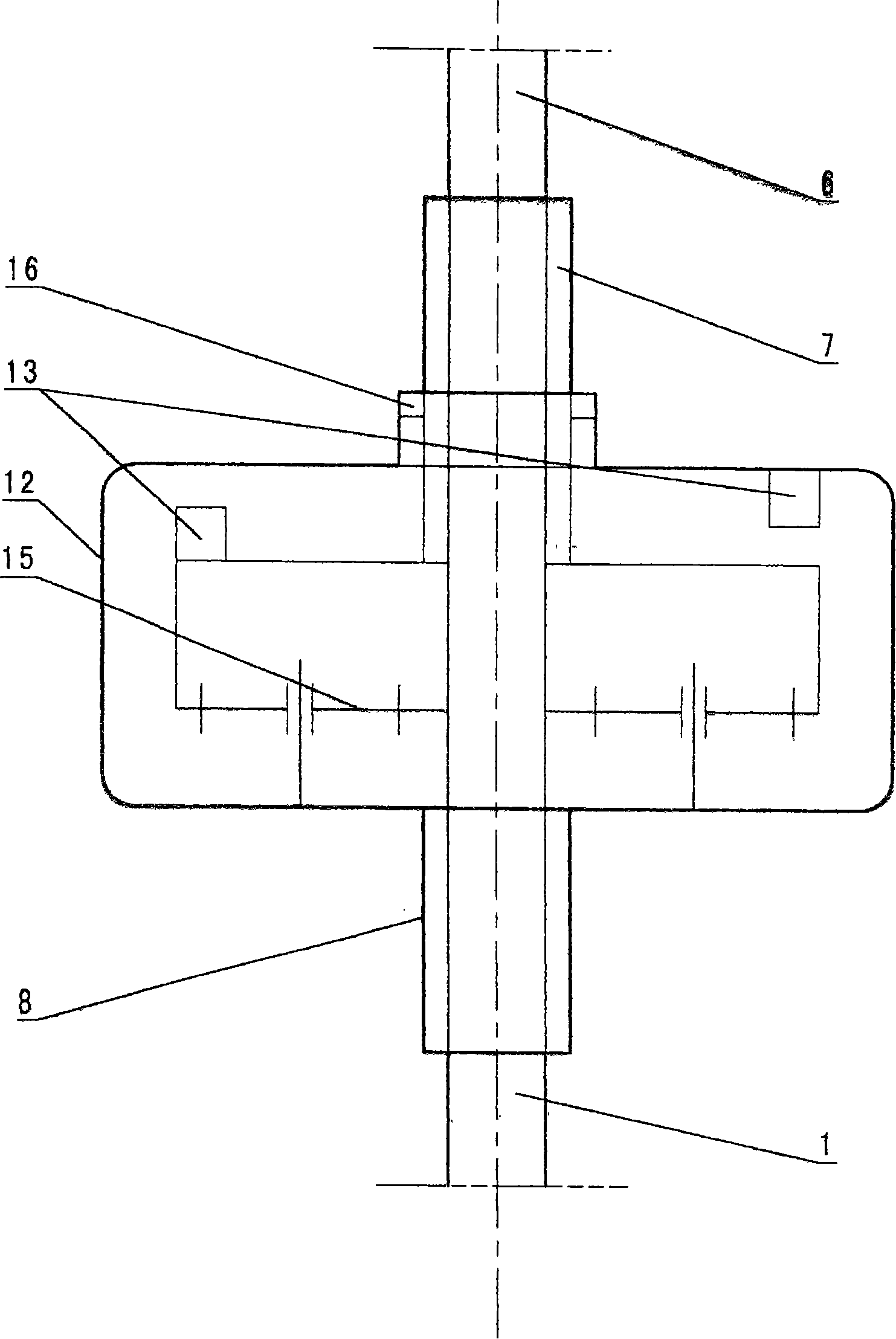
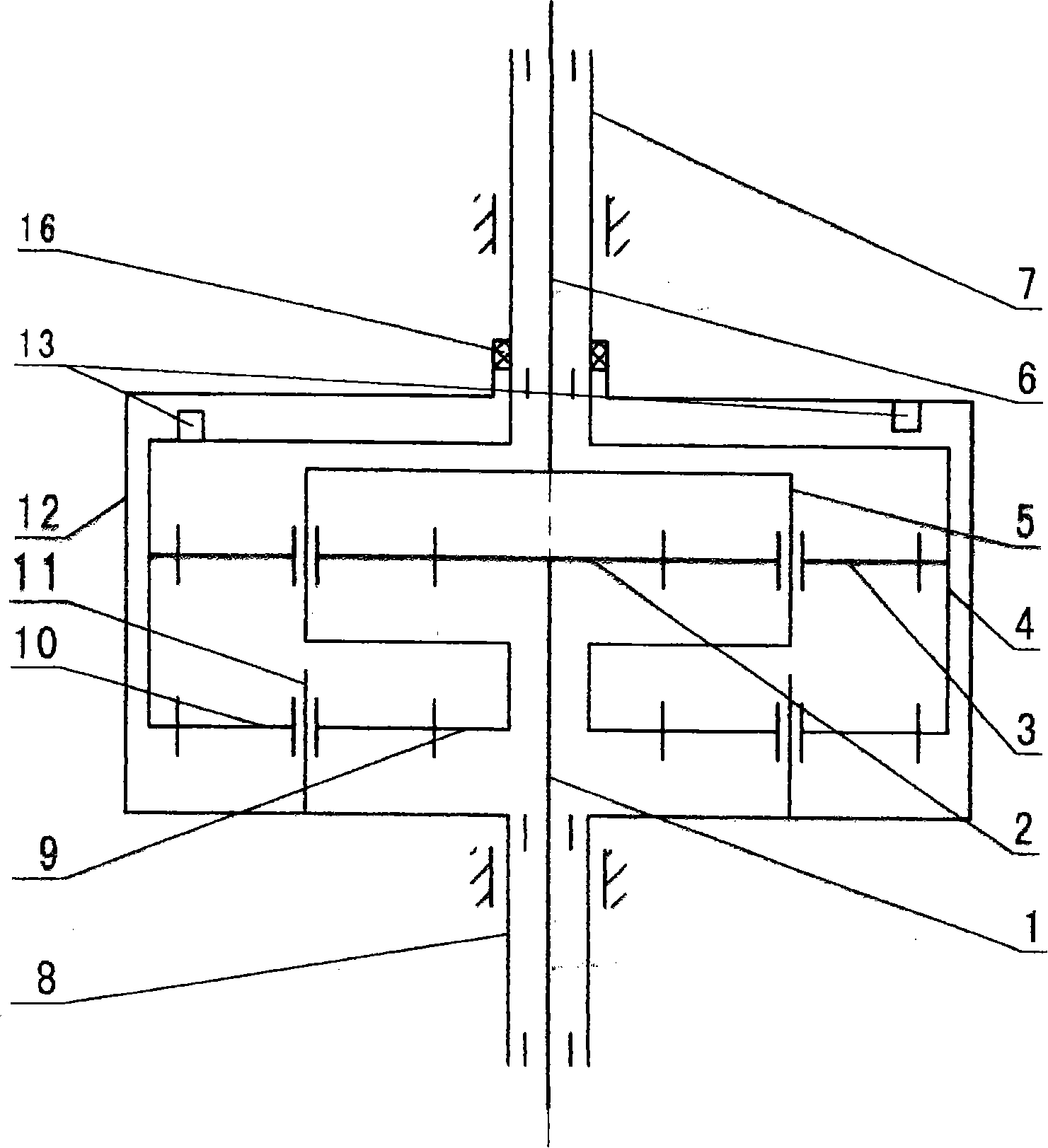
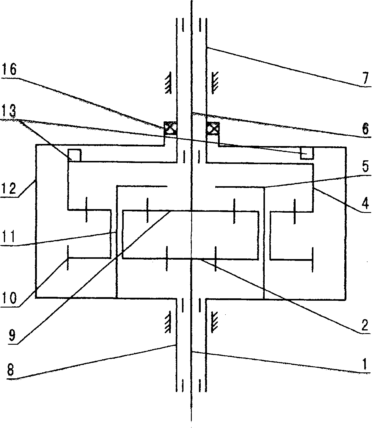
[0031] 1. Combine figure 1 The automatic deceleration clutch for washing machine is composed of input shaft 1, output shaft 6, output sleeve 7, input shaft sleeve 8, brake wheel 12 and dual drive gear mechanism 15 installed inside brake wheel 12. Input shaft 1 is installed in In the input shaft sleeve 8, the output shaft 6 is installed in the output shaft sleeve 7, the input shaft sleeve 8 is fixed on the lower end of the brake wheel 12, the planet shaft is fixed on the input shaft sleeve 8, the input shaft 1, the output shaft sleeve 7 The output shaft 6 and the output shaft 6 are respectively connected with the dual drive gear mechanism 15, and a clutch device 13 is installed between the brake wheel 12 and the output shaft sleeve 7. A sealing ring 16 is installed between the upper mouth of the brake wheel 12 and the output sleeve 7 to prevent the double drive gear mechanism 15 from being polluted by the outside world, and to prevent the double drive gear mechanism 15 from slippi...


PUM


Abstract

The invention relates to a full-automatic decelerating clutch for a washing machine, belonging to the technical field of washing machines, comprising an input shaft, an output shaft, an output shaft housing, an input shaft housing, a brake wheel and a double drive gear mechanism. The invention is characterized in that: the double drive gear mechanism is arranged inside the brake wheel, and the input shaft, the output shaft housing and the output shaft are respectively connected with the double drive gear mechanism; the brake wheel and the output shaft housing are reverse mutually, are dual-way driven in proportion, repeatedly swing and rotate, and rub and swing with a relative strength; under a dehydration working condition, via the locking function of the clutch, the output shaft is automatically combined with the output shaft housing, and simultaneously the output shaft and the output shaft housing continuously rotate with high speed in an unidirectional way, and the centrifugal dehydration is processed. The invention has the advantages of boasting simple structure, improving the performance of a decelerating clutch for a conventional washing machine, simplifying the structure of control system, reducing the noise of the washing machine and improving the efficacy and the service life of the washing machine.

Description

Technical field: [0001] The technical solution created by the present invention relates to the technical field of washing machines, in particular to a deceleration clutch of washing machines. Background technique: [0002] The existing conventional deceleration clutch is mainly composed of an input shaft, an output shaft, an output shaft sleeve, an input shaft sleeve, a brake wheel, a speed reduction mechanism installed inside the brake wheel, and a clutch component installed on the input shaft sleeve. In washing conditions, the output shaft is required to rotate repeatedly in both directions at low speed. The output shaft sleeve and brake wheel of a conventional deceleration clutch are integrated. The deceleration mechanism generally only plays a simple deceleration effect. When the brake wheel is braked, the output The shaft sleeve is also braked, and the bidirectional rotation of the drive motor can only drive the output shaft to rotate in both directions. In the existing coun...

Claims


Application Information

Patent Timeline
Patent Type & Authority Applications(China)
IPC IPC(8): D06F37/36F16H1/28
Inventor 刘军薛华林
Owner NINGGUO JULONG IND
Why Eureka
Try Eureka