


Quick Research
Generate reliable direction feasibility study reports for your R&D in just a few steps.

Technical Q&A
Discover and master advanced knowledge NOW. Basics, ideas, possibilities, all at once.

Find Solutions
As an expert in R&D theories, this can generate solutions to your technical problems instantly.

Evaluate Feasibility
Analyze your overall solution with one click, know your potential R&D risks in advance.

Monitor Landscape
Get weekly tech updates, stay abreast of the latest tech innovations and key insights.
Tin wave generating machine impeller
A generator and impeller technology, applied in the direction of tin feeding device, metal processing equipment, manufacturing tools, etc., can solve the problems affecting the stability of tin wave, and achieve the effect of ensuring stability, simple structure and novel design
- Summary
- Abstract
- Description
- Claims
- Application Information
AI Technical Summary
Problems solved by technology
Method used
Image

Examples
Embodiment Construction
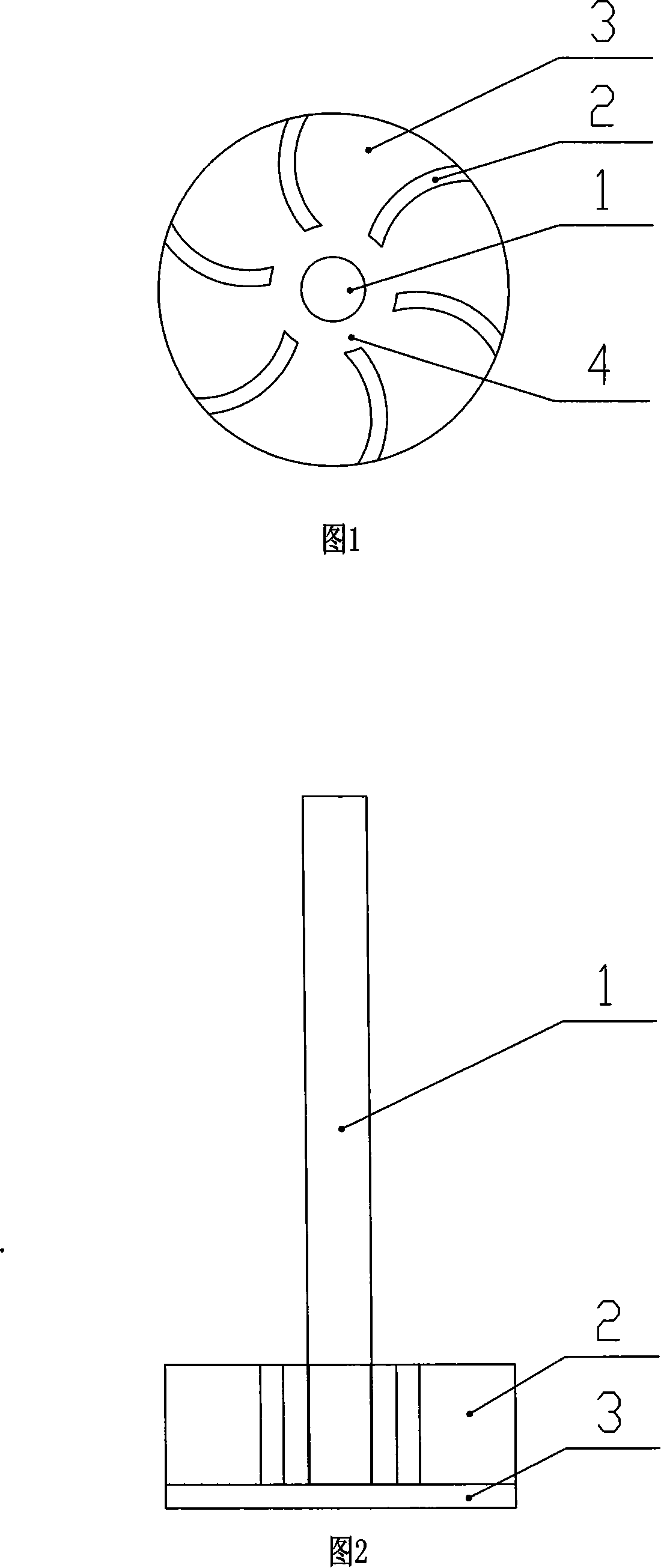
[0011] A tin wave generator impeller as shown in Fig. 1 and Fig. 2 has a rotating shaft 1 and blades 2, and the blades 1 have an arc surface structure and are 6 in number. The end of the rotating shaft 1 is fixedly provided with a circular blade fixing plate 3 , the blades 2 are evenly distributed on the blade fixing plate 3 , and there is a gap 4 between the tail of the blade 1 and the rotating shaft 2 .
[0012] When in use, the motor drives the impeller, the impeller rotates, and a negative pressure is formed in the inner cavity near the tin inlet hole, and the external tin liquid is sucked into the inner cavity through the tin inlet hole, and the tin liquid first reaches the gap 4, and then separates the area according to each blade The reserved amount of tin liquid is evenly distributed to each blade separation area, and the tin liquid in the blade separation area is thrown out of the inner cavity from the tin outlet hole under the action of centrifugal force with the rota...
PUM
 Abstract
Description
Claims
Application Information
 - R&D Engineer
- R&D Manager
- IP Professional
- Industry Leading Data Capabilities
- Powerful AI technology
- Patent DNA Extraction
Browse by: Latest US Patents, China's latest patents, Technical Efficacy Thesaurus, Application Domain, Technology Topic, Popular Technical Reports.
© 2024 PatSnap. All rights reserved.Legal|Privacy policy|Modern Slavery Act Transparency Statement|Sitemap|About US| Contact US: help@patsnap.com