Filter units for exhaust hoods

A technology of filter and exhaust hood, which is applied in the direction of filtration separation, dispersed particle filtration, application, etc.

Active Publication Date: 2011-12-14
BOSCH SIEMENS HAUSGERATE GMBH
View PDF6 Cites 0 Cited by
  • Summary
  • Abstract
  • Description
  • Claims
  • Application Information

AI Technical Summary

Problems solved by technology

Therefore, the cleaning of the grease collecting filter is also very difficult

Method used


Image

  • Filter units for exhaust hoods
  • Filter units for exhaust hoods
  • Filter units for exhaust hoods

Examples


Embodiment Construction

[0036] exist figure 1 An exemplary embodiment of a filter arrangement 1 according to the invention in the installed state in an exhaust hood 2 is shown in . The exhaust hood 2 has an outer shell 3 and a vapor screen 4 arranged below the outer shell 3 . Operating elements such as, for example, switches 5 are provided on the front side of the vapor screen 4 . Furthermore, it is shown that a lighting element 6 is provided on the underside of the vapor screen 4 .

[0037] Formed in the underside of the vapor screen 4 is a suction opening 7 surrounded by a screen 8 which extends towards the suction opening 7 . Water vapor or vapor thus flowing towards the underside of the vapor screen 4 can be directed towards the suction opening 7 . The suction port 7 is covered by the filter device 1 .

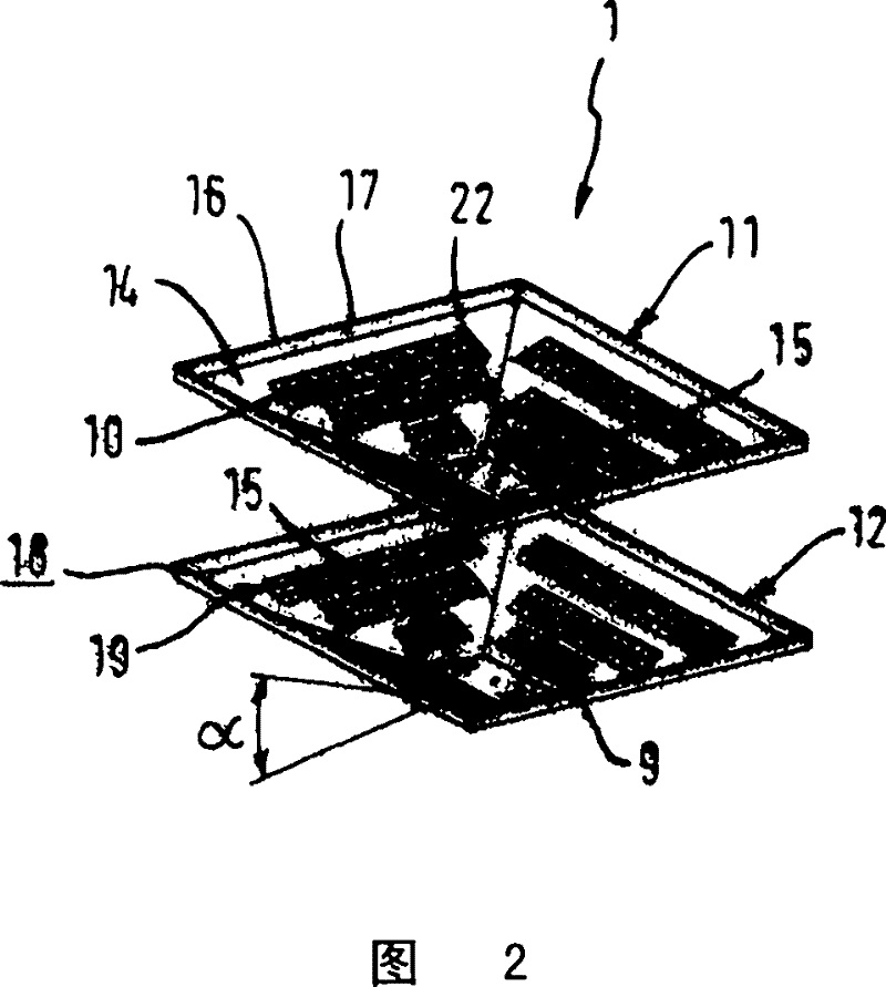
[0038] The filter device 1 has a square truncated pyramid shape with edges protruding downward from the suction opening 7 . In the exemplary embodiment shown, the collection container 13 is...


PUM


Abstract

A filter assembly (1), which separates particles and liquid droplets from the airflow (W) passing through the cooker extraction hood, comprises two dished shells (11, 12). These are detachably connected. One shell (12) carries a spacer (18). The sheet-metal construction of the shells includes filter openings. These are located in the side walls of each shell, which are bent-up from the base (9). Openings in adjacent shells are mutually-offset. At least some of the openings are round holes. Around their edges, nozzle geometries are formed. These formations are integral with the shells. The shells are coated (e.g. with PTFE) and their overall shape is blunt-pyramidal.

Description

technical field [0001] The invention relates to a filter arrangement for an exhaust hood for separating particles and / or liquid droplets from an air flow flowing through a filter arrangement consisting of at least two housing parts located in one another. Background technique [0002] A filter arrangement of this type is known, for example, from DE197536871. The filter device described there is a conically constructed grease filter made of multilayer expanded metal. The individual expanded metal layers are connected in the edge region by disk rings. [0003] A disadvantage of this filter arrangement is the deposition of particles, for example dust or gum-containing oils, in and between the individual expanded metal layers. Therefore, high water pressures and / or high temperatures are required for cleaning the filter device. [0004] Another filter arrangement is described in DE2720201C2. The filter device is a grease collection grate in which lamellae are used which are ...

Claims


Application Information

Patent Timeline
Patent Type & Authority Patents(China)
IPC IPC(8): B01D45/08F24C15/20
CPCB01D45/08F24C15/2035B01D46/00B01D35/00
Inventor E·费斯塔梅尔U·赖夫D·罗斯曼
Owner BOSCH SIEMENS HAUSGERATE GMBH
Why Eureka
Try Eureka