Organic electroluminescent device

An electroluminescent device, organic technology, applied in the direction of electroluminescent light source, electric light source, electrical components, etc., can solve the problems of easy pollution of evaporation chamber, poor high temperature stability, unfavorable storage and use of OLED devices, etc., and achieve improvement Effects of improving luminous efficiency and thermal stability and reducing chance

Inactive Publication Date: 2008-04-16
TSINGHUA UNIV +2
View PDF0 Cites 13 Cited by
  • Summary
  • Abstract
  • Description
  • Claims
  • Application Information

AI Technical Summary

Problems solved by technology

But F 4 -TCNQ itself is volatile and easily contaminates the evaporation chamber, and F 4 - The high temperature stability of TCNQ is poor, which is not conducive to the storage and use of OLED devices at high temperatures

Method used


Image

  • Organic electroluminescent device
  • Organic electroluminescent device
  • Organic electroluminescent device

Examples


Embodiment 1

[0033] Embodiment 1: (part number OLED-1)

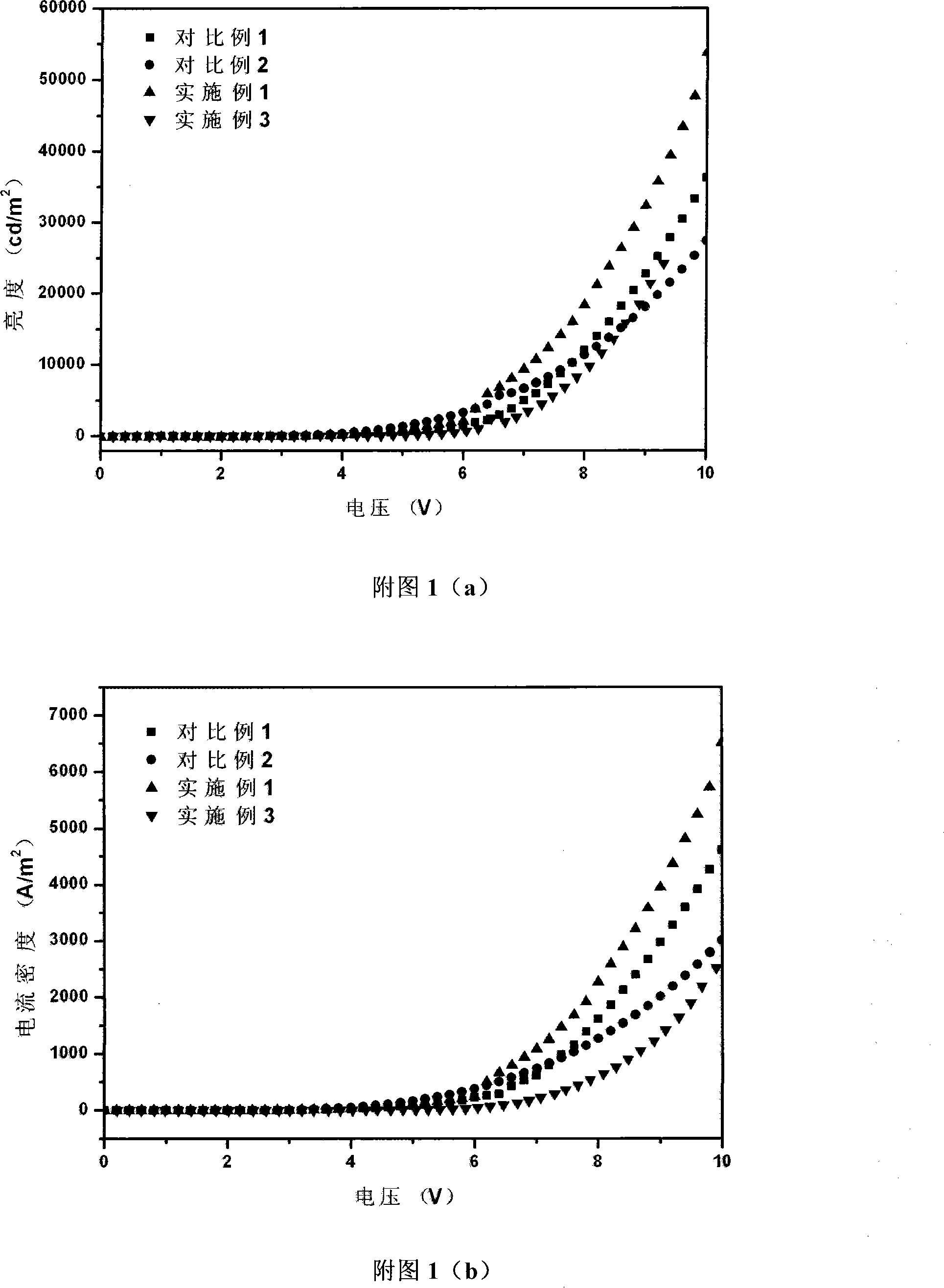
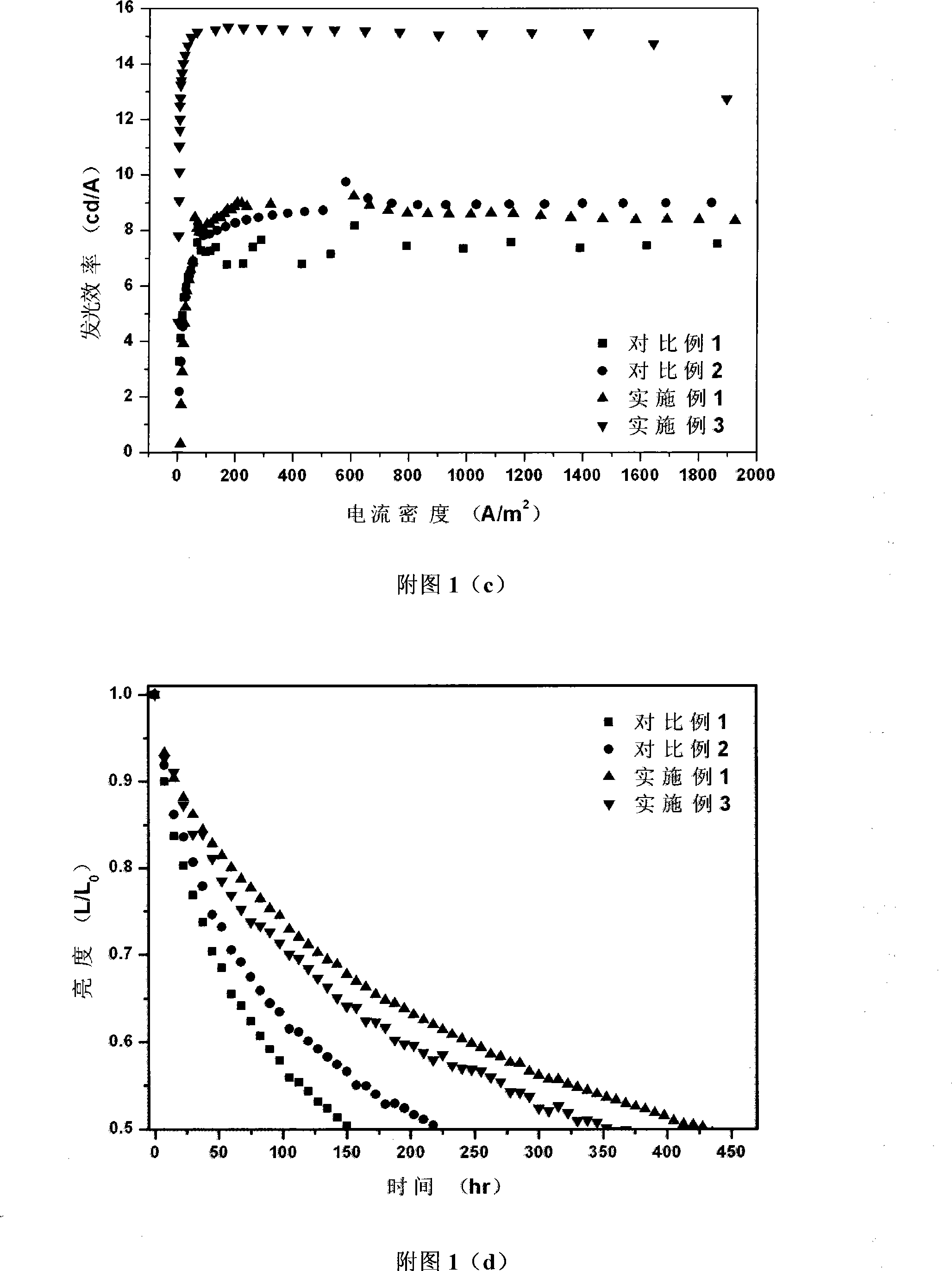
[0034] Glass / ITO / m-MTDATA (120nm): BiF 3 [50%] / NPB(30nm) / Alq 3 (30nm): C545T[1%] / Alq 3 (20nm) / LiF(0.5nm) / Al(200nm) (1)

[0035] The specific preparation method of the organic electroluminescent device with the above structural formula (1) is as follows:

[0036] ① Clean the glass substrate by using boiling detergent ultrasonic and deionized water ultrasonic method, and place it under the infrared lamp to dry, and evaporate a layer of anode material on the glass with a film thickness of 80-280nm;

[0037] ②Place the above-mentioned glass substrate with anode in a vacuum chamber, and evacuate to 1×10 -5 pa Continue to evaporate the hole injection layer on the above-mentioned anode layer film, and use the double-source co-evaporation method to evaporate m-MTDATA and BiF 3 , the evaporation rate of both is 0.1nm / s, the total evaporation film thickness is 120nm, BiF 3 The doping concentration in m-MTDATA is 50wt%;

[0038] ③On the ...

Embodiment 2

[0042] Embodiment 2: (part number OLED-2)

[0043] Glass / ITO / m-MTDATA (120nm): Bi 2 o 3 [50%] / NPB(30nm) / Alq 3 (30nm): C545T[1%] / Alq 3 (20nm) / LiF(0.5nm) / Al(200nm) (2)

[0044] The preparation method is the same as in Example 1, except that the doping material is replaced by Bi when preparing the hole injection layer in step 2. 2 o 3 .

Embodiment 3

[0045] Embodiment 3: (part number OLED-3)

[0046] Glass / ITO / m-MTDATA (120nm): Sm 2 (CO 3 ) 3 [50%] / NPB(30nm) / Alq 3 (30nm): C545T[1%] / Alq 3 (20nm) / LiF(0.5nm) / Al(200nm) (3)

[0047] The preparation method is the same as in Example 1, except that the doping material is changed to Sm when preparing the hole injection layer in step 2. 2 (CO 3 ) 3 .


PUM


Abstract

The invention relates to an organic electroluminescent part comprising an anode, a cathode and an organic functional layer arranged between the two electrodes; at least one of a hole infusion layer and a hole transmission layer contains matrix and mixed material; the mixed material is inorganic insulation material and chosen from the metal halide, metal oxide or metal carbonate. The invention overcomes the defect that the present OLED part is not very stable and the service life is short; with the structure of mixing insulation material in the part, the luminescent rate of part is effectively promoted and at the same time, the structure is beneficial to relieving the aging of working parts; the thermal stability of the part is properly increased and the service life of the part is greatly prolonged.

Description

technical field [0001] The present invention relates to an organic electroluminescent device (OLED), more particularly to an organic electroluminescent device having a doped hole transport layer and / or hole injection layer. Background technique [0002] Organic electroluminescent displays have a series of advantages such as self-illumination, low-voltage DC drive, full curing, wide viewing angle, light weight, simple composition and process, etc. Compared with liquid crystal displays, organic electroluminescent displays do not need a backlight source Large, low power, and its response speed can reach 1000 times that of liquid crystal displays, but its manufacturing cost is lower than that of liquid crystal displays with the same resolution. Therefore, organic electroluminescent displays have broad application prospects. [0003] The general structure of an organic electroluminescent device includes in turn: a substrate, an anode, an organic layer, and a cathode, and the orga...

Claims


Application Information

Patent Timeline
Patent Type & Authority Applications(China)
IPC IPC(8): H05B33/14H05B33/12
Inventor 邱勇谢静段炼
Owner TSINGHUA UNIV
Why Eureka
Try Eureka