
Method and receiver to increase the spectral efficiency of dpsk modulation format

A modulation format and receiver technology, used in electromagnetic receivers, electromagnetic transceivers, phase-modulated carrier systems, etc.

Inactive Publication Date: 2008-04-16
ALCATEL LUCENT SAS
View PDF2 Cites 5 Cited by
  • Summary
  • Abstract
  • Description
  • Claims
  • Application Information

AI Technical Summary

Problems solved by technology

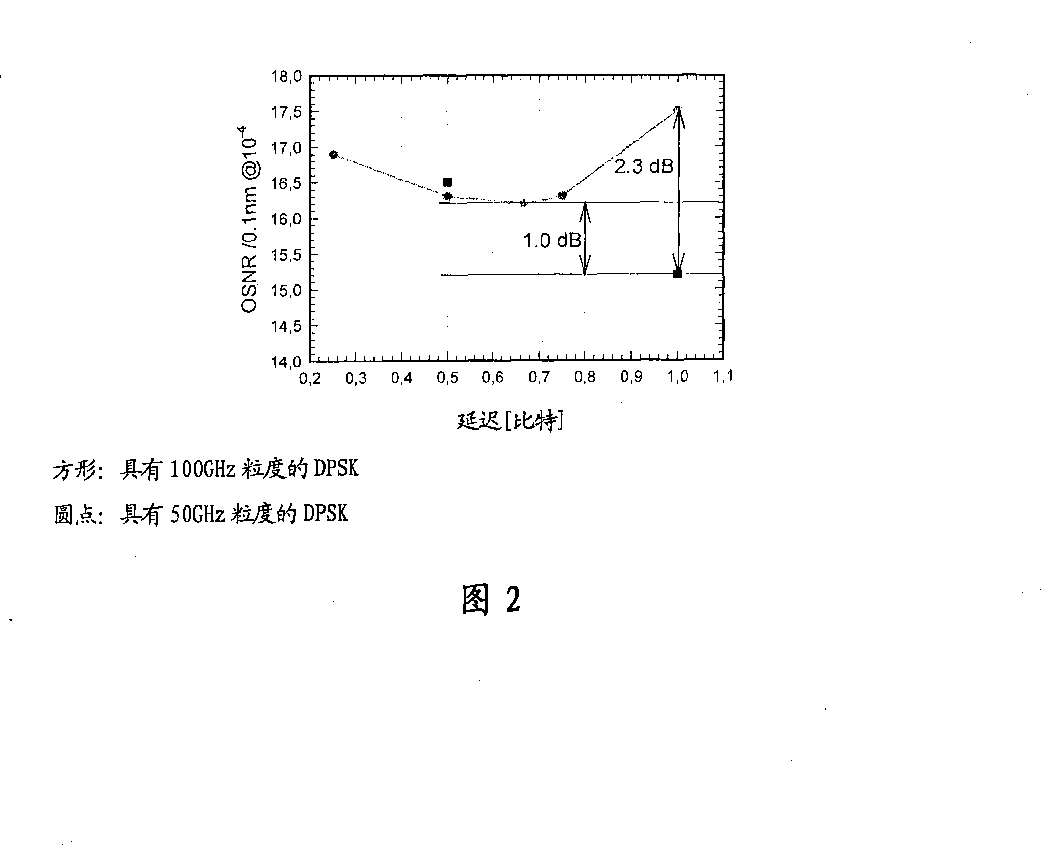
The document also mentions that the delay can vary by other than exactly one bit while still providing sufficient delay

Method used


Image

  • Method and receiver to increase the spectral efficiency of dpsk modulation format
  • Method and receiver to increase the spectral efficiency of dpsk modulation format

Examples


Embodiment Construction

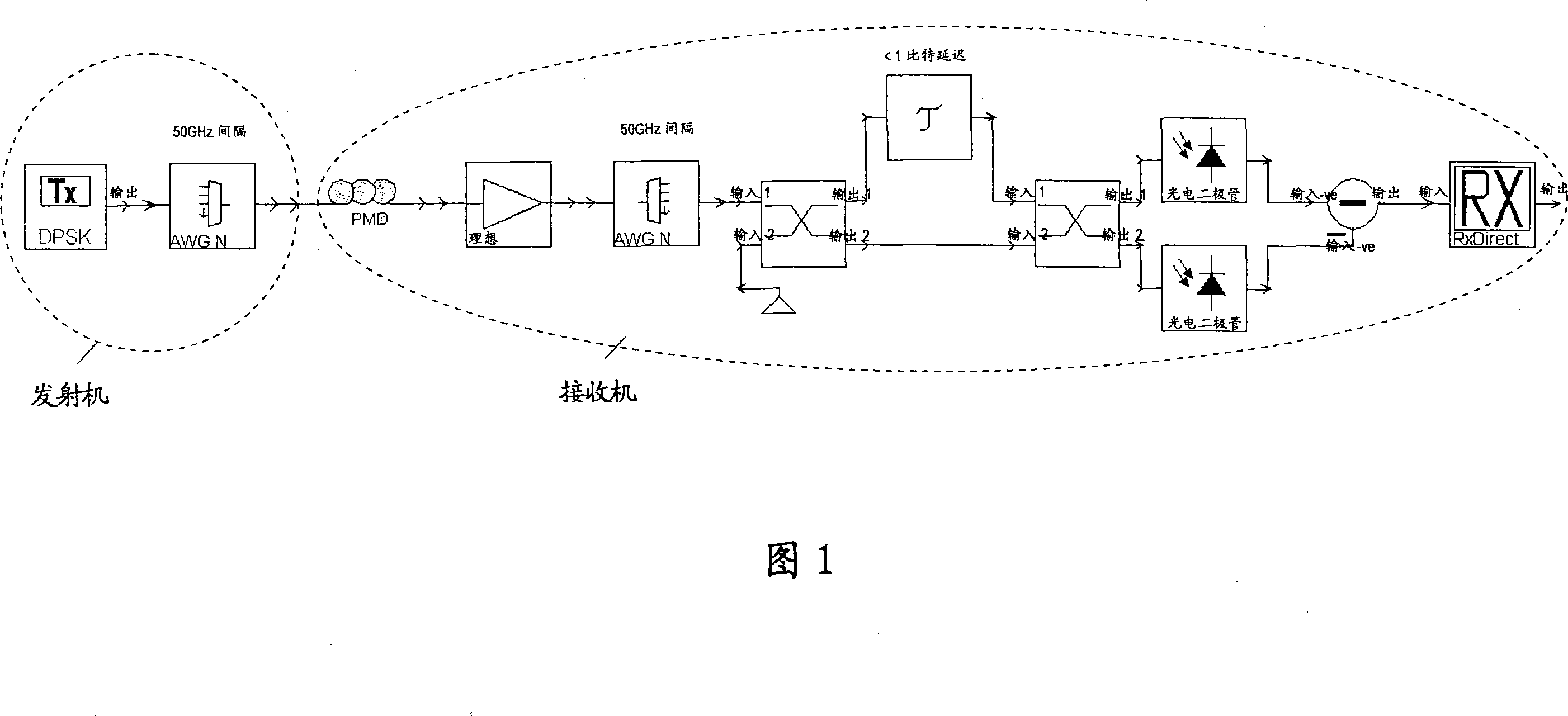
[0014] For modulation formats such as Optical Duobinary (ODB), Differential Phase Shift Keying (DPSK) and Differential Quadrature Phase Shift Keying (DQPSK), a logical exclusive OR (or modulo 2 addition ). Since realizing such a device in the electronic field causes many difficulties, it has been proposed to realize such a function in the optical field using an optical delay line interferometer (DLI).

[0015] Optical DLI is a simple device used in the following way in the prior art. The incoming optical signal is split into two paths. The signal in one path is delayed by a time corresponding to one bit, and the signals in both paths are coherently recombined. Typically, each division and recombination is performed in a respective optical 3dB coupler, in which case the DLI has two outputs corresponding to the coherent summation and summation of the optical signal and the delayed optical signal, respectively Difference. Thus, if the optical signal and the delayed optical si...


PUM


Abstract

The optical DPSK demodulator converts phase into amplitude variations by delaying one path of an interferometer by one bit period. This operation includes a differentiation of the transmitted signal, which must be counteracted by applying a precoder at the TX side. By variation of the delay within the interferometer the differentiation will be changed. A reduction of the delay results in an emphasis of higher frequencies. This can be used to counteract the low pass behaviour (after detection) produced by narrowband optical filters. A penalty reduction from >2 dB to ~1 dB is expected.

Description

technical field [0001] The present invention relates to a method for demodulating optical dense wavelength division multiplexed / DWDM / signals transmitted over an optical transmission system using differential phase shift keying / DPSK / modulation format. Furthermore, the invention relates to a receiver for optical dense wavelength division multiplexed / DWDM / signals transmitted over an optical fiber link using a differential phase shift keying / DPSK / modulation format, the receiver comprising a filter for filtering using an optical delay line The device / DLF / optical DPSK demodulator that converts the phase of the optical DWDM signal into an amplitude change. Background technique [0002] The input data stream of an optical transmission system can be viewed as a succession of light pulses representing digital bits. The bit rates of current optical transmission systems typically range from 10 Giga bits per second (Gb / s) to 40 Gb / s, resulting in optical pulses (or bit periods) that are...

Claims


Application Information

Patent Timeline
Patent Type & Authority Applications(China)
IPC IPC(8): H04B10/158H04L27/22H04J14/02H04B10/2581H04B10/43
CPCH04J14/0279H04J14/0246H04J14/0227H04J14/02H04B10/677H04B10/2581H04B10/556H04B10/60
Inventor B·弗朗茨
Owner ALCATEL LUCENT SAS
Learn More